Diagnostic Repair Manual
Replacement Parts
Safety
Table of Contents
57-59
Electromagnetic Induction
Magnetism
Electromagnetic Fields
More Sophisticated AC Generator
Simple AC Generator
Generator Operating Diagram
Line Breakers 120 VAC only
Field Boost
Generator AC Connection System
Connection for 120/240 VAC Dual Voltage
LIC Grit or Abrasive to Clean Slip Rings
Rotor Assembly
General
Battery Charge Components
Brush Holder
Excitation Circuit Components
Voltage Regulator
Adjust POT LED
Adjustment Procedure
162
Control Panel Components
Control Panel Component Identification
Insulation Resistance Testers
Cleaning the Generator
Effects of Dirt and Moisture
Drying the Generator
Stator SHORT-TO-GROUND Tests
Brushing and Vacuum Cleaning
Stator Insulation Resistance
Cloth or Compressed AIR
Megohmmeter
Testing Rotor Insulation
Measuring DC Voltage
Meters
VOM
Measuring AC Voltage
Measuring Resistance
Measuring AC Frequency
Measuring Current
Ohms LAW
Electrical Units
Circuit CONDITION- OFF
Introduction
Operational Analysis
Circuit CONDITION- PRE-HEAT
Circuit CONDITION- Cranking
Circuit CONDITION-RUNNING
Circuit CONDITION- Shutdown
Circuit CONDITION- Fault Shutdowns
Engine Control Circuit Board
Battery
Adding Water
Effects of Temperature
Checking Battery State of Charge
Charging a Battery
Starter Contactor & Motor
Preheat Switch
START/STOP Switch
AMP Fuse
Glow Plugs
Engine Governor
Fuel Injection Pump
Fuel NOZZLES/INJECTORS
Overspeed Protection
LOW OIL Pressure Switch High Coolant Temperature Switch
Adapter LOW OIL Pressure Switch
Engine Protective Devices
Troubleshooting Flowcharts
Troubleshooting Flowcharts
Problem 3 No Battery Charge Output
Troubleshooting Flowcharts
Troubleshooting Flowcharts
Troubleshooting Flowcharts
Troubleshooting Flowcharts
Troubleshooting Flowcharts
Test 1- Check NO-LOAD Voltage Frequency
Test 2 Check & Adjust
Test 4- Fixed Excitation TEST/ROTOR AMP Draw
Test 3- Test Excitation Circuit Breaker
Set a VOM to its Rx1 scale
Test 5- Wire Continuity
Re-connect Wire 11 and Wire 22 to the Voltage Regulator
Test 6- Check Field Boost
Model QP75D
Test 7 Test Stator DPE Winding
184W
Test 8- Check Sensing Leads / Power Windings
Test 9- Check Brush Leads
159W
Test 10 Check Brushes & Slip Rings
Test 11- Check Rotor Assembly
Tance Tests Procedure
Test 14- Check Load Watts & Amperage
Test 15 Check Battery Charge Output
Test 12 Check Main Circuit Breaker
Test 13- Check Load Voltage Frequency
Short to Ground
Test 16 Check Battery Charge Rectifier
Battery Charge Rectifier BCR is a full wave rectifier
Test 20- Check Fuel Pump
Test 19- Test PRE-HEAT Switch
Set a VOM to read battery voltage 12 VDC
Test 18 TRY Cranking the Engine
Test 21- Check 14 AMP Fuse
Test 22- Check Battery & Cables
Test 23- Check Power Supply to Circuit Board
Disconnect the connector from the wires of the fuel pump
Not Activated
Test 24 Check START-STOP Switch
Conditions Affecting Starter Motor Performance
Test 26- Test Starter Contactor
Test 27 Check Starter Motor
Measuring Current
Checking the Pinion
Pinion
Tools for Starter Performance Test
Starter motor test bracket may be made as shown in Figure
Testing Starter Motor
Tachometer
Test Bracket
Test 28- Check Fuel Supply
Test 29 Check Wire 14 Power Supply
Test 30 Check Wire
If Wire 18 checks GOOD, proceed to Problem 8 Section
Test 34- Test D1 Diode
Test 32- Test Preheat Contactor
Test 33- Test Glow Plugs
Test 36- Fuel Injector Pump
Test 35- Check Valve Adjustment
Remove the valve cover from engine Disconnect the battery
Repeat Steps 1 through 8 on remaining cylinder
If fuel is noted, proceed to next step in flowchart
Adjust the regulated pressure on the gauge to 80 psi
Down Test / Compression Test
Test 39- Check Circuit Board for Ground
Test 38 Check OIL Pressure Switch
Test 40- Test Water Temperature Switch
Components for Short to Ground
Test 43 Check Wire 15 for Short to Ground
If continuity is measure, replace the switch
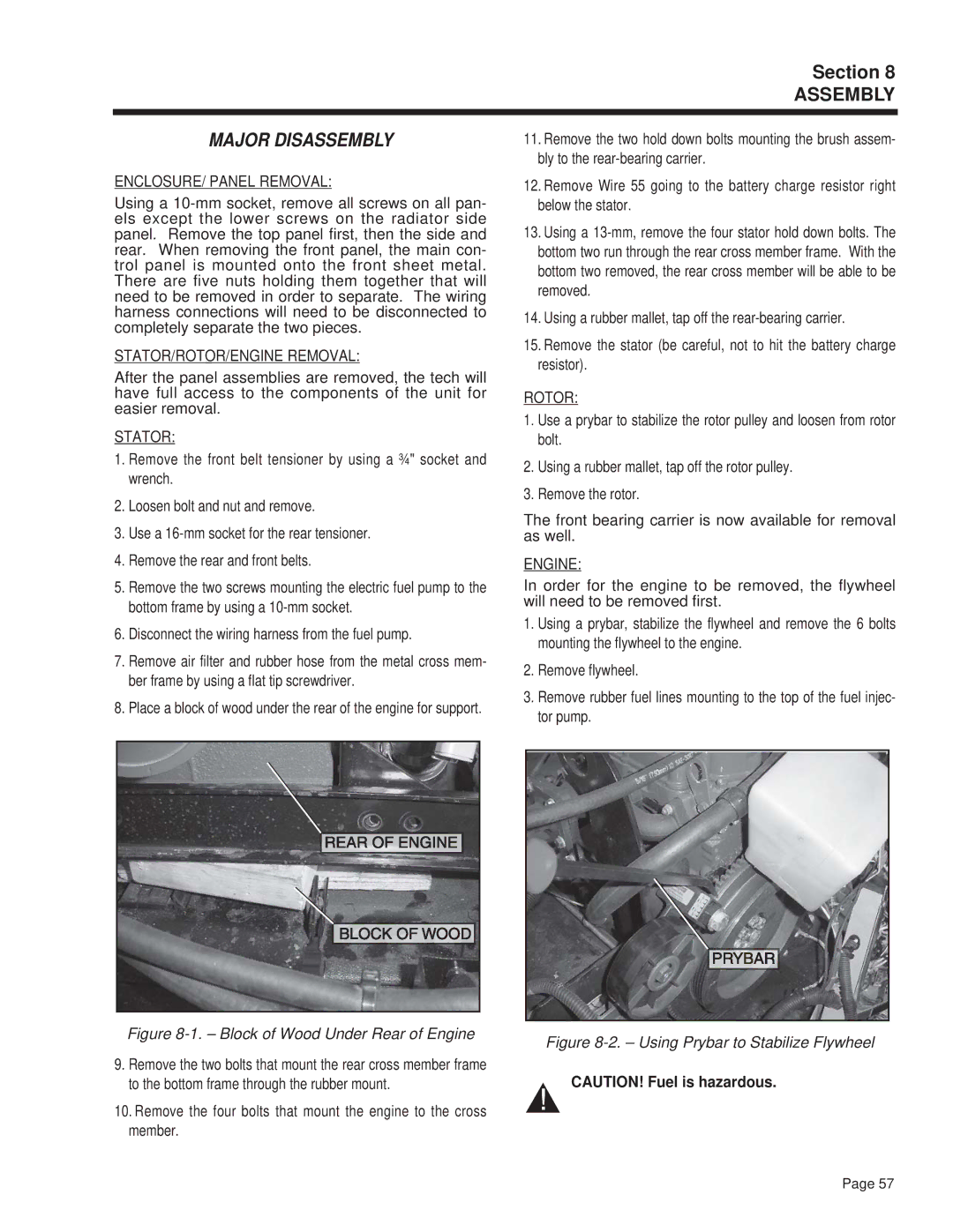
Major Disassembly
Belt Tensioning
RE-ASSEMBLY
FAN Belt
Line Corner UP Between 5˚ to 10˚
Section Exploded Views / Part Numbers
Bearing Carrier, Front
Rotor Assembly
Stator Assembly
Flywheel Assembly
Base Frame Drawing No D2357-A
Slide Latch Flush
Door, Service Rear
Door, Service Front
Base Frame Weldment
Enclosure Drawing No D2358-D
Decal, Battery +
Cover, Access Lift
Cover, Access Electrical
Gasket, Electrical Access
Views / Part
Cover Plate, Scroll Weldment
25 26
Wire Assembly #
Assembly, Potted Regulator
Assembly Marine Control Board
Rectifier, Battery Charging
Intake and Exhaust System Drawing No D2362-B
Hose, Air Inlet
Exhaust Gasket
Chamber Air Intake
Air Filter
Views / Part Numbers
Wire Assembly, Black #4 Ground
Fuel Pump Assembly
Boot, Battery Cable
Cable, Battery
Customer Controls Assembly Drawing No D2364-D
Boot, Circuit Breaker
Start / Stop Switch
Switch, Pushbutton Spst
Boot / Nut / Preheat Switch
Gear
Camshaft Assembly
Camshaft Gear
KEY
2630
Liter Diesel Cylinder Head Drawing No D2794
Liter Diesel Crankshaft, Piston and Flywheel Drawing No -B
OIL Pump Cover
Idler Gear Assembly
Spring
Thrust Washer
Exhaust Rocker ARM
Rocker ARM Assembly
Includes ALL Components Shown below
Intake Rocker ARM
Liter Diesel Injector Pump Drawing No -C
Tank Return Model 04270 To Injection Pump To Fuel Pump
27 25 19 18
HOUSING, Timing Gear
3114
Liter Diesel Water Pump Drawing No
Charts
Generator Specifications
Engine Specifications
Type Quietpact Model
ROTOR/STATOR Resistance Values
Page
Data
Data
Electrical Data
C4945
Schematic Drawing No C4945-A Model
C4946-A
Electrical
Sheet 2
OF4996 REV. O