Section 3
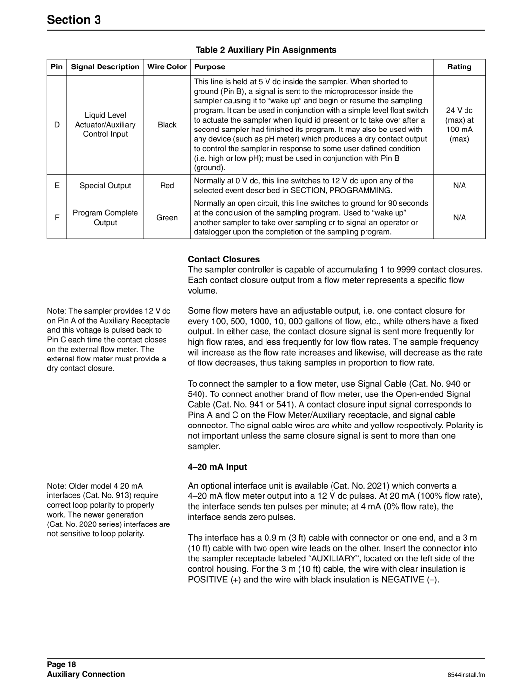
Table 2 Auxiliary Pin Assignments
Pin | Signal Description | Wire Color | Purpose | Rating | |
|
|
|
|
| |
|
|
| This line is held at 5 V dc inside the sampler. When shorted to |
| |
|
|
| ground (Pin B), a signal is sent to the microprocessor inside the |
| |
|
|
| sampler causing it to “wake up” and begin or resume the sampling |
| |
| Liquid Level |
| program. It can be used in conjunction with a simple level float switch | 24 V dc | |
|
| to actuate the sampler when liquid id present or to take over after a | (max) at | ||
D | Actuator/Auxiliary | Black | |||
second sampler had finished its program. It may also be used with | 100 mA | ||||
| Control Input |
| |||
|
| any device (such as pH meter) which produces a dry contact output | (max) | ||
|
|
| |||
|
|
| to control the sampler in response to some user defined condition |
| |
|
|
| (i.e. high or low pH); must be used in conjunction with Pin B |
| |
|
|
| (ground). |
| |
|
|
|
|
| |
E | Special Output | Red | Normally at 0 V dc, this line switches to 12 V dc upon any of the | N/A | |
selected event described in SECTION, PROGRAMMING. | |||||
|
|
|
| ||
|
|
|
|
| |
|
|
| Normally an open circuit, this line switches to ground for 90 seconds |
| |
F | Program Complete | Green | at the conclusion of the sampling program. Used to “wake up” | N/A | |
Output | another sampler to take over sampling or to signal an operator or | ||||
|
|
| |||
|
|
| datalogger upon the completion of the sampling program. |
| |
|
|
|
|
|
Note: The sampler provides 12 V dc on Pin A of the Auxiliary Receptacle and this voltage is pulsed back to Pin C each time the contact closes on the external flow meter. The external flow meter must provide a dry contact closure.
Note: Older model
(Cat. No. 2020 series) interfaces are not sensitive to loop polarity.
Contact Closures
The sampler controller is capable of accumulating 1 to 9999 contact closures. Each contact closure output from a flow meter represents a specific flow volume.
Some flow meters have an adjustable output, i.e. one contact closure for every 100, 500, 1000, 10, 000 gallons of flow, etc., while others have a fixed output. In either case, the contact closure signal is sent more frequently for high flow rates, and less frequently for low flow rates. The sample frequency will increase as the flow rate increases and likewise, will decrease as the rate of flow decreases, thus taking samples in proportion to flow rate.
To connect the sampler to a flow meter, use Signal Cable (Cat. No. 940 or 540). To connect another brand of flow meter, use the
4–20 mA Input
An optional interface unit is available (Cat. No. 2021) which converts a
The interface has a 0.9 m (3 ft) cable with connector on one end, and a 3 m (10 ft) cable with two open wire leads on the other. Insert the connector into the sampler receptacle labeled “AUXILIARY”, located on the left side of the control housing. For the 3 m (10 ft) cable, the wire with clear insulation is POSITIVE (+) and the wire with black insulation is NEGATIVE
Page 18 |
|
Auxiliary Connection | 8544install.fm |