number of specialty speaker cables preferred by perfec- tionists. If you have 4 ohm speakers, larger wire is recom- mended than for the typical 8 ohm speakers, too.
The black output terminals are connected to ground in- ternally. The black terminals may be connected together (common ground) when in the normal stereo mode, to utilize headphone junction boxes, or other accessories employing a common ground system.
It is important that the red terminals never be connected
together when operating in stereo. Thus it is important that you carefully observe the proper connections when using a common ground device, to be sure there is no reversal.
In the special case where the amplifier has been inter- nally modified to convert it to monophonic bridged opera- tion, with the addition of the
ASSEMBLY
There are three basic rules for success in electronic kit building:
1.Read the instructions carefully, and follow them in or- der.
2.Make secure solder connections which are bright and smooth.
3.Check your work carefully after each step.
The
Kit building should be fun, and we are certain you will find this to be so. Assembly will be faster, easier, and more enjoyable if you have someone help you by reading the steps aloud, selecting the required parts, and preparing the necessary wire lengths in advance as you proceed. Fatigue increases the risk of error, so take a break rather than push to early completion. There are relatively few separate components in this design, to make it easy to pack every- thing away, if need be.
Your work area should have good lighting, the proper tools, and a place where the large pictorial diagram can be tacked to the wall within easy reach for checking. The tools should include:
1.A 40 to 60 watt pencil soldering iron with a 306” or smaller tip which reaches 700°F.
2.60/40 (60% tin) ROSIN CORE solder , l/16” diameter or smaller.
3.A damp sponge or cloth to wipe the hot tip of the iron.
INSTRUCTIONS
4.A wire stripping tool for removing insulation. This can be a
5.A
6.A #l or #2 Phillips head screwdriver.
7.
8.Diagonal or
9.Large “gas” or
10.A 1/4"
A soldering “gun” is not recommended. The unfamiliar user is more likely to damage the etched circuit boards with its higher heat potential and unbalanced weight. Also, because he may not wait long enough for it to reach operat- ing temperature each time it is switched on, poor solder connections are more likely. Pencil irons are much lighter and easier to use, and there is no waiting time when solder connections follow in sequence, as in kit building. Make sure you have a holder for it, though, and always unplug it when you take a break.
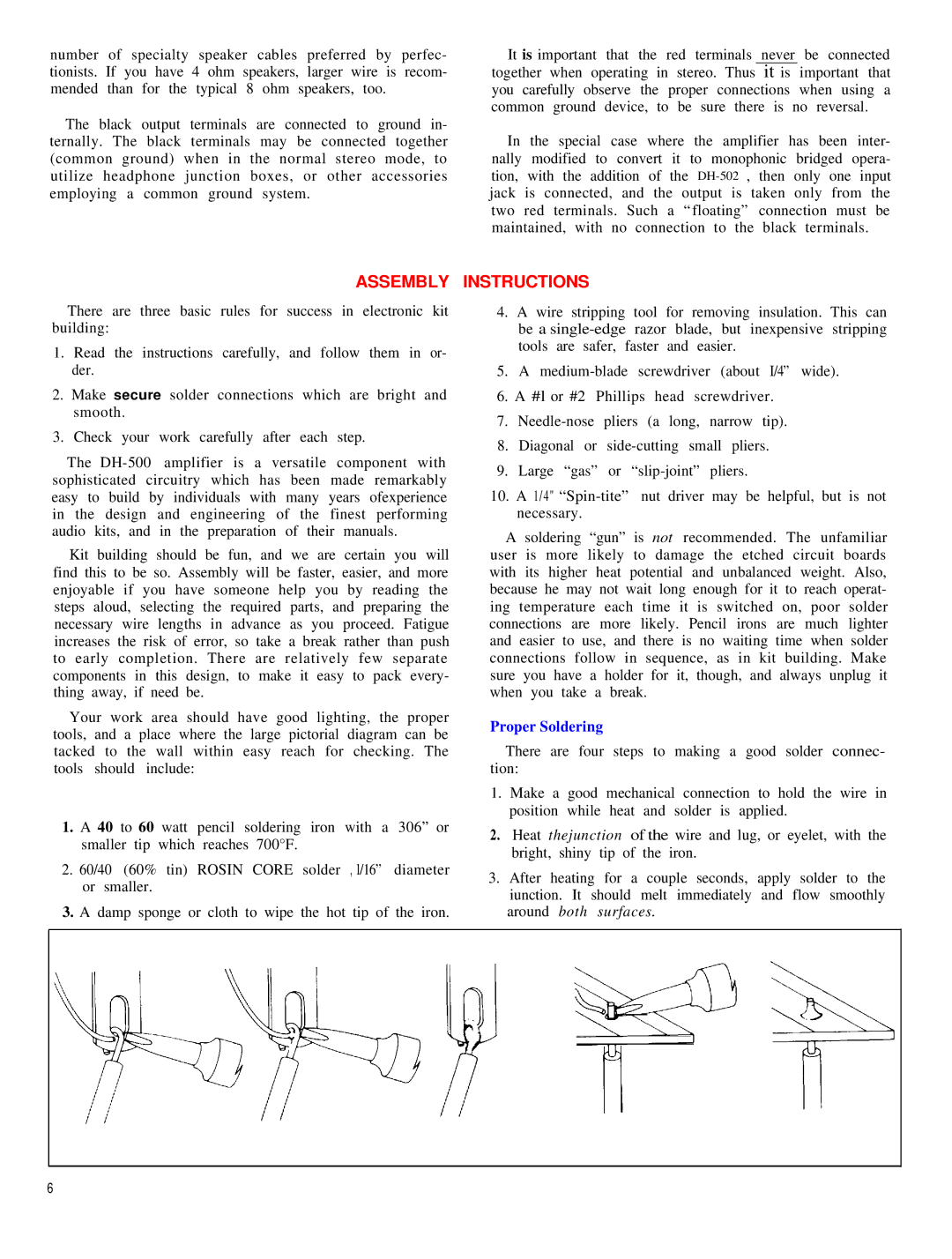
Proper Soldering
There are four steps to making a good solder connec- tion:
1.Make a good mechanical connection to hold the wire in position while heat and solder is applied.
2.Heat thejunction of the wire and lug, or eyelet, with the bright, shiny tip of the iron.
3.After heating for a couple seconds, apply solder to the iunction. It should melt immediately and flow smoothly around both surfaces.
6