Installation Procedure
1. BEFORE INSTALLATION | <Don't discard any accessories until comp> |
Determine the way to carry unit to installation place.
Don't remove packing until unit reaches installation place.
If unpacking is unkavoidable, protect unit properly.
2. SELECTION OF INSTALLATION PLACE
(1) Installation place shall meet the following and agreed by customers:
Place where proper air flow can be ensured.
No block to air flow.
Water drainage is smpoth.
Place strong enough to support unit weight.
Place where inclination is not evident on ceiling.
Enough space for mainenance.
Indoor and outdoor unit piping length is within limit. (Refer to Installation Manual for outdoor unit.) Indoor and outdoor unit, power cable, inter unit cable are at least 1 m away fromT.V. radop. This is helpful to avoid picture disturbance and noise. (Even if 1 m iskept, noise can still appear if radio wave is strong)
(2)Ceiling height
Indoor unit can be installed on ceiling of
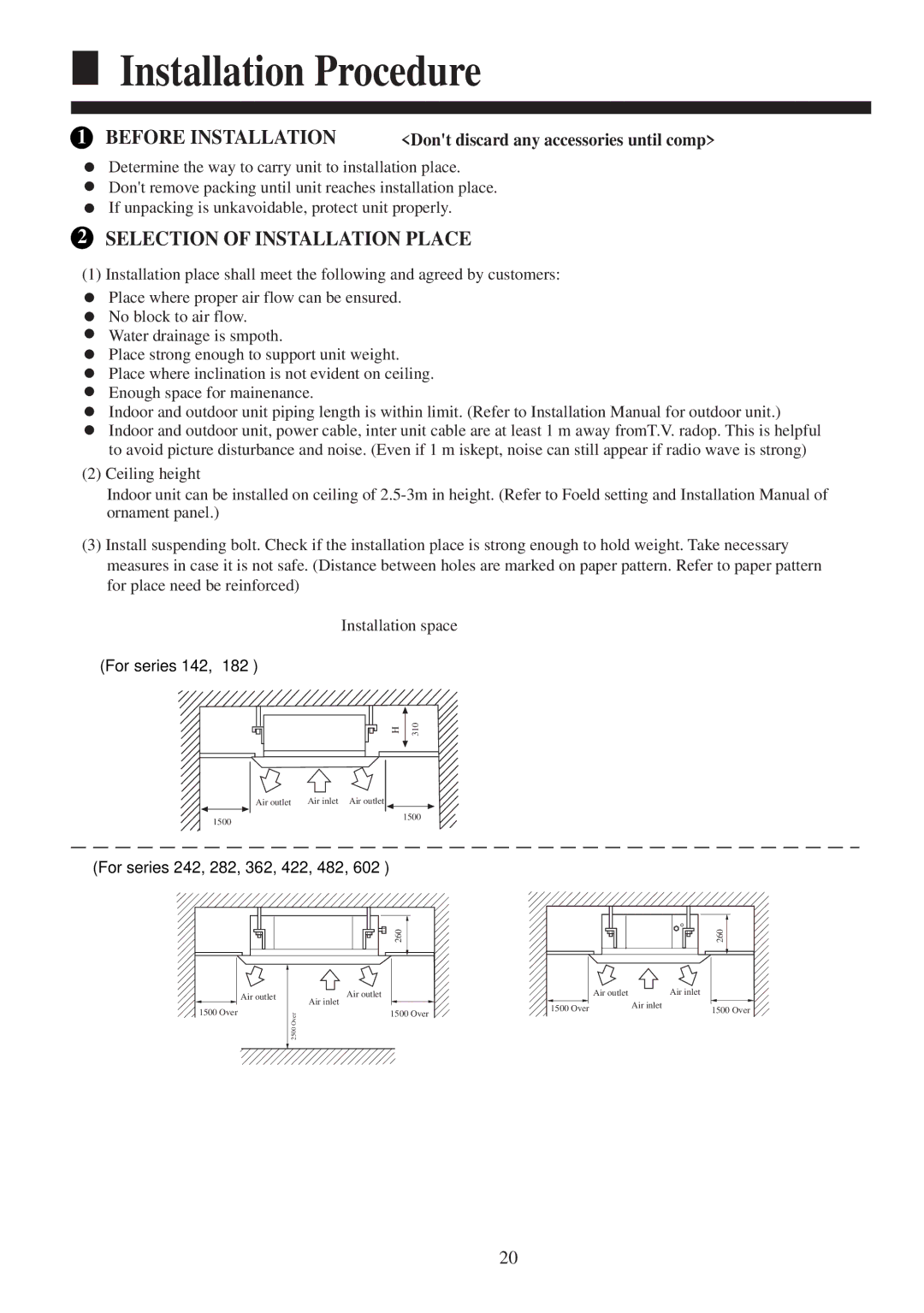
(3)Install suspending bolt. Check if the installation place is strong enough to hold weight. Take necessary measures in case it is not safe. (Distance between holes are marked on paper pattern. Refer to paper pattern for place need be reinforced)
Installation space
(For series 142, 182 )
H
310
|
| Air outlet | Air inlet Air outlet |
|
|
|
|
|
| 1500 | |
1500 |
|
|
| ||
|
|
|
|
| |
(For series 242, 282, 362, 422, 482, 602 )
260 |
Air outlet |
| Air outlet |
1500 Over |
| Air inlet |
2500 Over | 1500 Over | |
|
|
260 |
Air outlet |
| Air inlet |
1500 Over | Air inlet | 1500 Over |
|
20