Installation Procedure
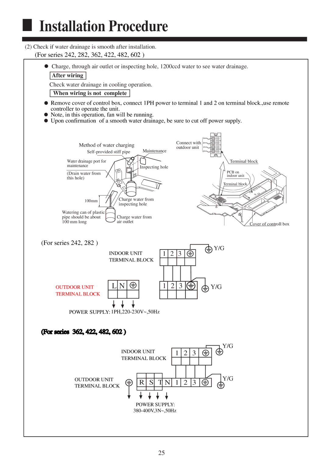
(2)Check if water drainage is smooth after installation.
(For series 242, 282, 362, 422, 482, 602 )
Charge, through air outlet or inspecting hole, 1200ccd water to see water drainage.
After wiring
Check water drainage in cooling operation.
When wiring is not complete
![]() Remove cover of control box, connect 1PH power to terminal 1 and 2 on terminal block.,use remote controller to operate the unit.
Remove cover of control box, connect 1PH power to terminal 1 and 2 on terminal block.,use remote controller to operate the unit.
![]() Note, in this operation, fan will be running.
Note, in this operation, fan will be running.
![]() Upon confirmation of a smooth water drainage, be sure to cut off power supply.
Upon confirmation of a smooth water drainage, be sure to cut off power supply.
Method of water charging
Maintenance | |||
Water drainage port for |
|
| |
maintenance |
| Inspecting hole | |
|
| ||
(Drain water from |
|
| |
this hole) |
|
| |
100mm | Charge water from | ||
inspecting hole | |||
| |||
Watering can of plastic | Charge water from | ||
pipe should be about | |||
100 mm long | air outlet |
| |
Connect with | 1 |
2 | |
outdoor unit | 3 |
| D |
Terminal block
PCB on indoor unit
Terminal block
Cover of controll box
(For series 242, 282 )
OUTDOOR UNIT TERMINAL BLOCK
INDOOR UNIT TERMINAL BLOCK
L N ![]()
![]()
![]()
1 | 2 | Y/G |
3 |
1 2 3 


 Y/G
Y/G
POWER SUPPLY:
(For series 362, 422, 482, 602 )
| INDOOR UNIT |
|
|
|
|
|
|
|
|
|
|
|
|
|
|
|
| Y/G | |||||||||||
|
| 1 | 2 | 3 |
|
|
|
|
|
|
|
|
|
|
|
| |||||||||||||
|
|
|
|
|
|
|
|
|
|
|
|
|
| ||||||||||||||||
OUTDOOR UNIT | TERMINAL BLOCK |
|
|
|
|
|
|
|
|
|
|
|
|
|
|
|
| Y/G | |||||||||||
|
|
|
|
|
|
|
|
|
|
|
|
|
|
|
| ||||||||||||||
|
|
|
|
|
|
|
|
|
|
|
|
|
|
|
|
|
|
|
|
|
|
|
|
|
|
| |||
|
|
|
|
|
|
|
|
|
|
|
|
|
|
|
|
|
|
|
|
|
|
|
|
|
|
| |||
|
|
|
|
|
|
|
|
|
|
|
|
|
|
|
|
|
|
|
|
|
|
|
|
|
|
| |||
TERMINAL BLOCK |
|
| R | S |
| T | N |
| 1 | 2 | 3 |
|
|
|
|
|
|
|
|
|
|
|
| ||||||
|
|
|
|
|
|
|
|
|
|
|
|
|
|
|
|
|
|
|
|
|
|
|
|
|
|
|
|
| |
|
|
|
|
|
|
|
|
|
|
|
|
|
|
|
|
|
|
|
|
|
|
|
|
|
|
|
|
|
|
|
|
|
|
|
|
|
|
|
|
|
|
|
|
|
|
|
|
|
|
|
|
|
|
|
| ||||
|
|
|
|
|
|
|
|
|
|
|
|
|
|
|
|
|
|
|
|
|
|
|
|
|
|
|
|
|
|
|
| POWER SUPPLY: |
|
|
|
|
|
|
|
|
|
|
|
|
|
|
|
|
| ||||||||||
|
|
|
|
|
|
|
|
|
|
|
|
|
|
|
|
|
| ||||||||||||
25