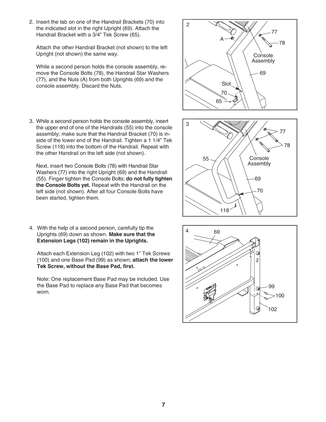
2. Insert the tab on one of the Handrail Brackets (70) into | 2 |
| |
the indicated slot in the right Upright (69). Attach the |
| ||
| 77 | ||
Handrail Bracket with a 3/4” Tek Screw (65). |
| ||
| A | ||
|
| ||
Attach the other Handrail Bracket (not shown) to the left |
| 78 | |
|
| ||
Upright (not shown) the same way. |
| Console | |
While a second person holds the console assembly, re- |
| Assembly | |
|
| ||
move the Console Bolts (78), the Handrail Star Washers |
| 69 | |
(77), and the Nuts (A) from both Uprights (69) and the |
| Slot | |
console assembly. Discard the Nuts. |
| ||
|
| ||
|
| 70 | |
|
| 65 | |
3. While a second person holds the console assembly, insert | 3 |
| |
the upper end of one of the Handrails (55) into the console |
| ||
| 77 | ||
assembly; make sure that the Handrail Bracket (70) is in- |
| ||
|
| ||
side of the lower end of the Handrail. Tighten a 1 1/4” Tek |
| 78 | |
Screw (118) into the bottom of the Handrail. Repeat with |
| ||
the other Handrail on the left side (not shown). | 55 | Console | |
| |||
Next, insert two Console Bolts (78) with Handrail Star |
| Assembly | |
|
| ||
Washers (77) into the right Upright (69) and the Handrail |
|
| |
(55). Finger tighten the Console Bolts; do not fully tighten |
| 69 | |
the Console Bolts yet. Repeat with the Handrail on the |
| 70 | |
left side (not shown). After all four Console Bolts have |
| ||
been started, tighten them. |
|
| |
|
| 118 | |
4. With the help of a second person, carefully tip the | 4 | 69 | |
Uprights (69) down as shown. Make sure that the | |||
|
| ||
Extension Legs (102) remain in the Uprights. |
|
|
Attach each Extension Leg (102) with two 1” Tek Screws (100) and one Base Pad (99) as shown; attach the lower
Tek Screw, without the Base Pad, first.
Note: One replacement Base Pad may be included. Use |
|
the Base Pad to replace any Base Pad that becomes | 99 |
worn. | 100 |
| |
| 102 |
7