ASSEMBLY
Assembly requires two persons. Set the treadmill in a cleared area and remove all packing materials. Do not dispose of the packing materials until assembly is completed.
Note: The underside of the treadmill walking belt is coated with
Assembly requires the included hex key ![]() and your own phillips screwdriver
and your own phillips screwdriver ![]()
![]() , and rub-
, and rub-
ber mallet ![]() . For help identifying the assembly hardware, see the drawings below. The number in parentheses below each drawing is the key number of the part, from the PART LIST on pages 30 and 31. The number following the parentheses is the quantity needed for assembly. Note: Some small parts may have been preassembled. If a part is not in the parts bag, check to see if it has been preassembled. To avoid damag- ing plastic parts, do not use power tools for assembly.
. For help identifying the assembly hardware, see the drawings below. The number in parentheses below each drawing is the key number of the part, from the PART LIST on pages 30 and 31. The number following the parentheses is the quantity needed for assembly. Note: Some small parts may have been preassembled. If a part is not in the parts bag, check to see if it has been preassembled. To avoid damag- ing plastic parts, do not use power tools for assembly.
Nut | 3/8” Star | 1” Tek Screw | |
Washer | Lower Latch Shock Bolt | ||
|
| ||
Upper Latch Shock Bolt |
| Extension Leg Bolt | |
Console Bolt | |||
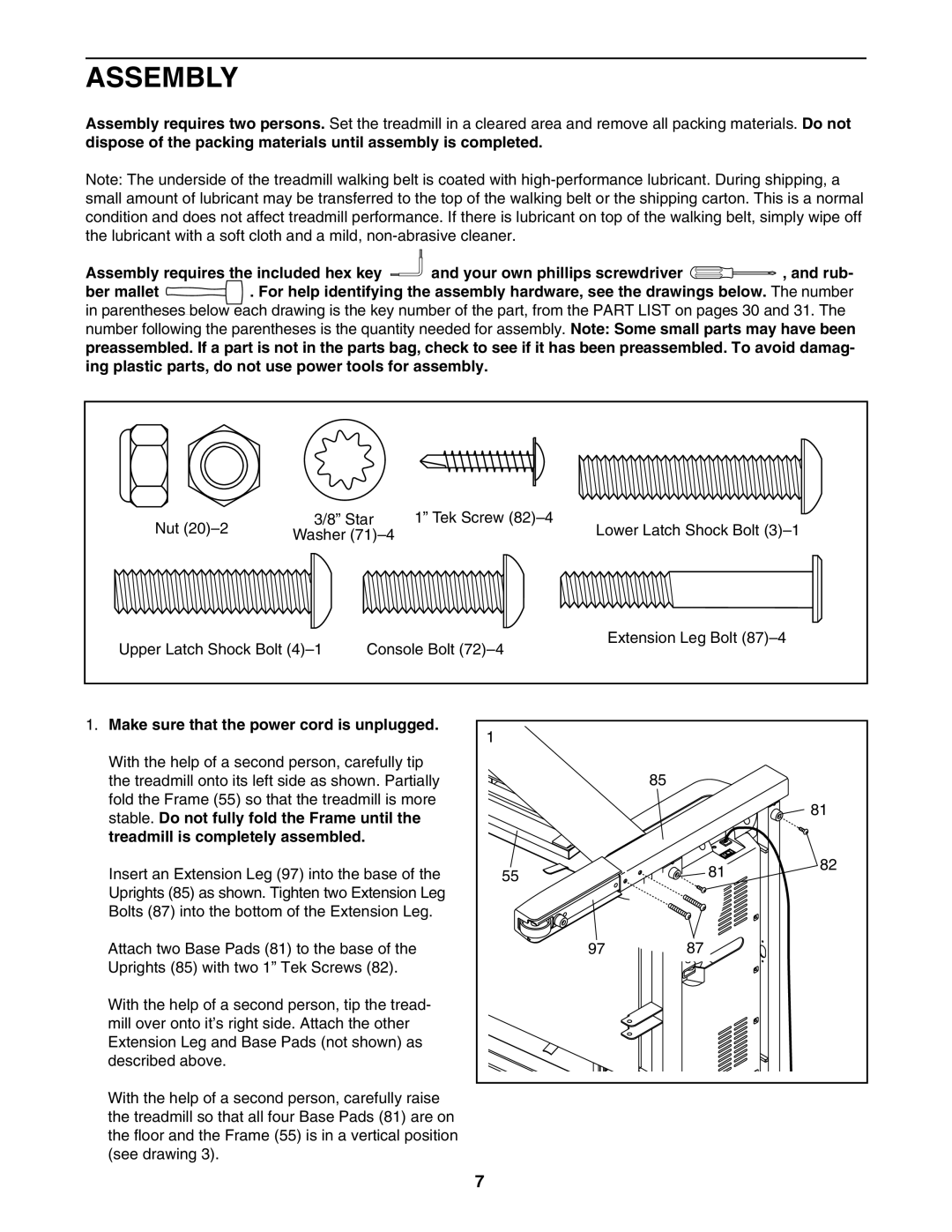
1. Make sure that the power cord is unplugged. | 1 |
|
|
|
|
|
|
| |
With the help of a second person, carefully tip |
|
|
|
|
the treadmill onto its left side as shown. Partially |
|
| 85 |
|
fold the Frame (55) so that the treadmill is more |
|
|
| 81 |
stable. Do not fully fold the Frame until the |
|
|
| |
|
|
|
| |
treadmill is completely assembled. |
|
|
|
|
Insert an Extension Leg (97) into the base of the | 55 |
| 81 | 82 |
|
| |||
Uprights (85) as shown. Tighten two Extension Leg |
|
|
|
|
Bolts (87) into the bottom of the Extension Leg. |
|
|
|
|
Attach two Base Pads (81) to the base of the |
| 97 | 87 |
|
Uprights (85) with two 1” Tek Screws (82). |
|
|
|
|
With the help of a second person, tip the tread- |
|
|
|
|
mill over onto it’s right side. Attach the other |
|
|
|
|
Extension Leg and Base Pads (not shown) as |
|
|
|
|
described above. |
|
|
|
|
With the help of a second person, carefully raise |
|
|
|
|
the treadmill so that all four Base Pads (81) are on |
|
|
|
|
the floor and the Frame (55) is in a vertical position |
|
|
|
|
(see drawing 3). |
|
|
|
|
| 7 |
|
|
|