ASSEMBLY
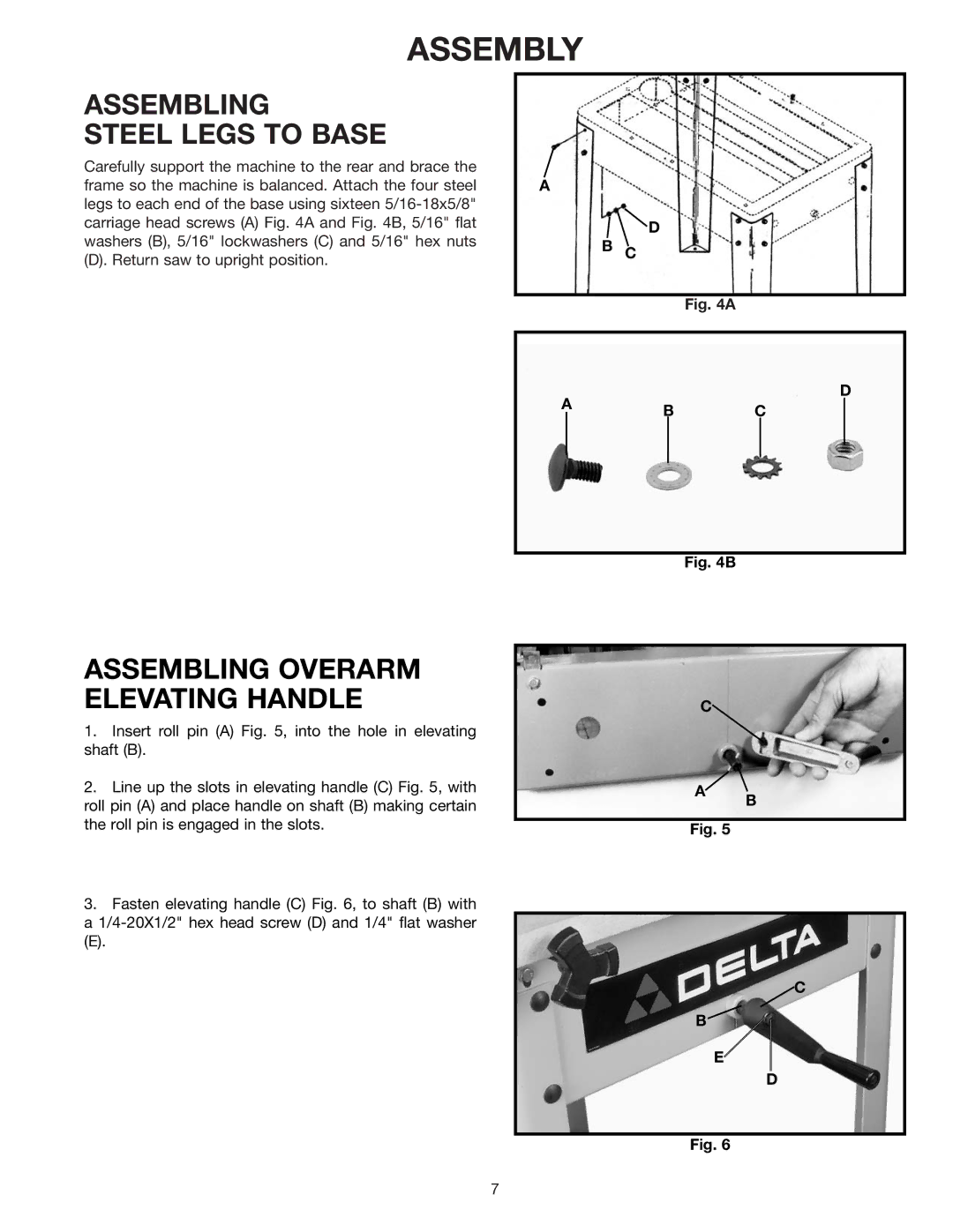
ASSEMBLING
STEEL LEGS TO BASE
Carefully support the machine to the rear and brace the frame so the machine is balanced. Attach the four steel legs to each end of the base using sixteen
(D). Return saw to upright position.
ASSEMBLING OVERARM ELEVATING HANDLE
1.Insert roll pin (A) Fig. 5, into the hole in elevating shaft (B).
2.Line up the slots in elevating handle (C) Fig. 5, with roll pin (A) and place handle on shaft (B) making certain the roll pin is engaged in the slots.
3.Fasten elevating handle (C) Fig. 6, to shaft (B) with a
(E).
A
D
B C
Fig. 4A
D
AB C
Fig. 4B
C
A![]()
B
Fig. 5
![]() C
C
B
E
D
Fig. 6
7