OPERATING CONTROLS AND ADJUSTMENTS
Every Delta Radial Saw is thoroughly tested, inspected and accurately aligned before leaving the factory, and when delivered is ready for operation after it is assembled. However, regardless of the care with which this or any piece of fine machinery is manufactured, inspected and shipped, it is possible that rough handling in shipment may make minor adjustments necessary. CAUTION: ALWAYS DISCONNECT SAW FROM POWER SOURCE BEFORE MAKING ANY
ADJUSTMENTS.
ON/OFF SWITCH
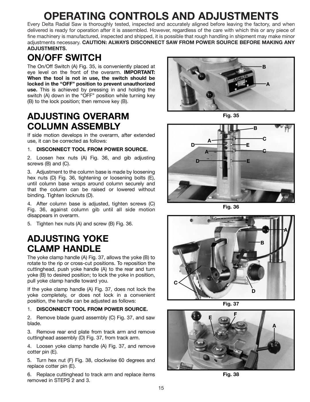
The On/Off Switch (A) Fig. 35, is conveniently placed at eye level on the front of the overarm. IMPORTANT:
When the tool is not in use, the switch should be locked in the “OFF” position to prevent unauthorized use. This is achieved by pressing in and holding the switch (A) down in the “OFF” position while turning key
(B) to the lock position; then remove key (B).
ADJUSTING OVERARM COLUMN ASSEMBLY
If side motion develops in the overarm, after extended use, it can be corrected as follows:
1.DISCONNECT TOOL FROM POWER SOURCE.
2.Loosen hex nuts (A) Fig. 36, and gib adjusting screws (B) and (C).
3.Adjustment to the column base is made by loosening hex nuts (D) Fig. 36, tightening or loosening bolts (E), until column base wraps around column securely and that the column can be raised or lowered without binding. Tighten locknuts (D).
4.After column base is adjusted, tighten screws (C) Fig. 36, against column gib until all side motion disappears in overarm.
5.Tighten hex nuts (A) and screw (B) Fig. 36.
ADJUSTING YOKE
CLAMP HANDLE
The yoke clamp handle (A) Fig. 37, allows the yoke (B) to rotate to the rip or
If the yoke clamp handle (A) Fig. 37, does not lock the yoke completely, or does not lock in a convenient position, the handle can be adjusted as follows:
B
A
Fig. 35
B
A![]()
![]() C
C
DE
AC
DE
Fig. 36
A
B
C
D
Fig. 37
1. | DISCONNECT TOOL FROM POWER SOURCE. |
2. | Remove blade guard assembly (C) Fig. 37, and saw |
blade. | |
3. | Remove rear end plate from track arm and remove |
cuttinghead assembly (D) Fig. 37, from track arm. | |
4. | Loosen yoke clamp handle (A) Fig. 37, and remove |
cotter pin (E). | |
5. | Turn hex nut (F) Fig. 38, clockwise 60 degrees and |
replace cotter pin (E). | |
E
F
A
6. Replace cuttinghead to track arm and replace items |
removed in STEPS 2 and 3. |
Fig. 38
15