DIAGRAM OF THE TELEVISION | Outdoor Antenna |
1 | 2 | 3 | 4 | 5 |
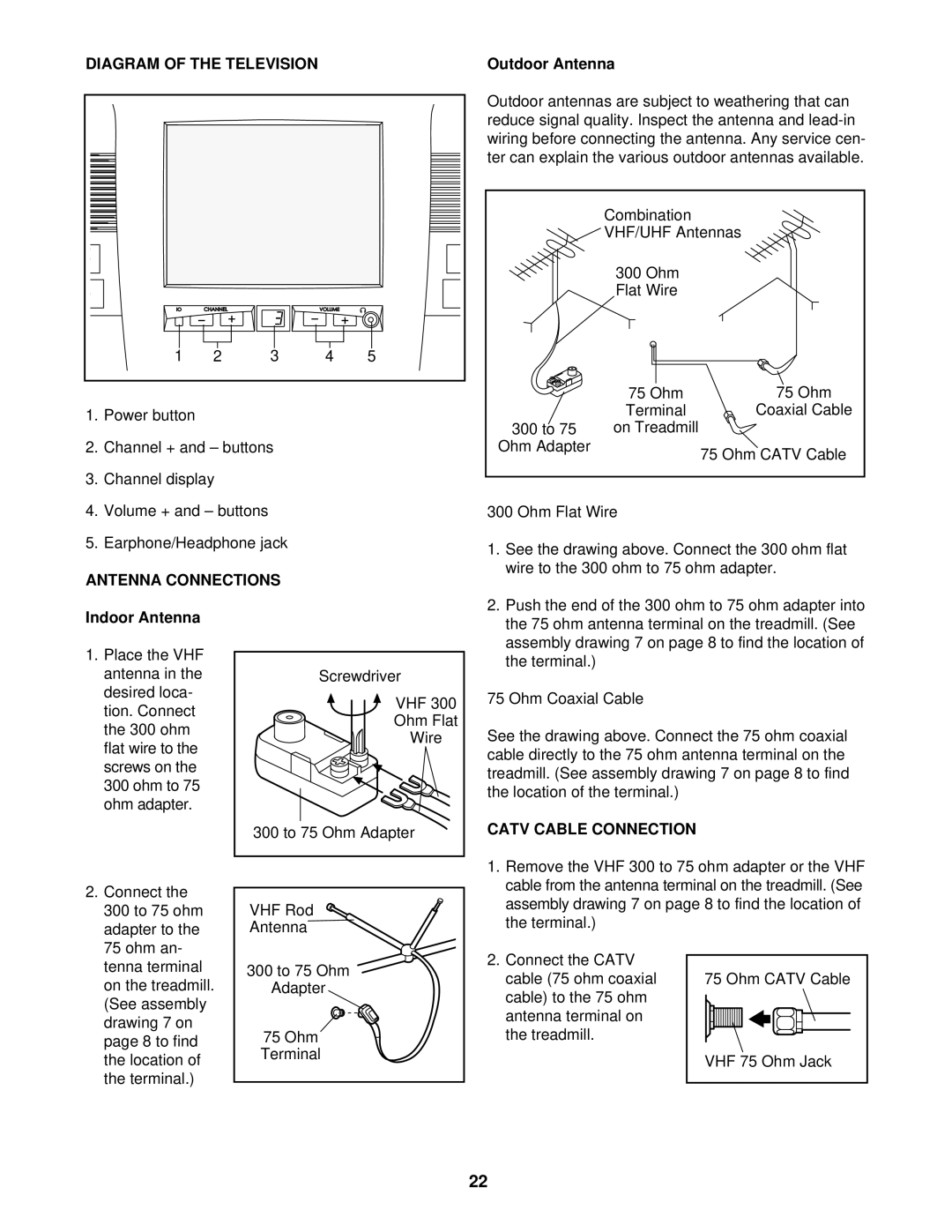
1.Power button
2.Channel + and – buttons
3.Channel display
4.Volume + and – buttons
5.Earphone/Headphone jack
ANTENNA CONNECTIONS
Indoor Antenna
Outdoor antennas are subject to weathering that can reduce signal quality. Inspect the antenna and
| Combination |
|
| VHF/UHF Antennas | |
| 300 Ohm |
|
| Flat Wire |
|
| 75 Ohm | 75 Ohm |
| Terminal | Coaxial Cable |
300 to 75 | on Treadmill |
|
Ohm Adapter |
| 75 Ohm CATV Cable |
|
| |
300 Ohm Flat Wire
1. | See the drawing above. Connect the 300 ohm flat |
| wire to the 300 ohm to 75 ohm adapter. |
2. | Push the end of the 300 ohm to 75 ohm adapter into |
| the 75 ohm antenna terminal on the treadmill. (See |
| assembly drawing 7 on page 8 to find the location of |
1.Place the VHF antenna in the desired loca- tion. Connect the 300 ohm flat wire to the screws on the 300 ohm to 75 ohm adapter.
Screwdriver |
VHF 300 |
Ohm Flat |
Wire |
300 to 75 Ohm Adapter |
the terminal.) |
75 Ohm Coaxial Cable
See the drawing above. Connect the 75 ohm coaxial cable directly to the 75 ohm antenna terminal on the treadmill. (See assembly drawing 7 on page 8 to find the location of the terminal.)
CATV CABLE CONNECTION
2. Connect the |
300 to 75 ohm |
adapter to the |
VHF Rod ![]()
![]() Antenna
Antenna
1.Remove the VHF 300 to 75 ohm adapter or the VHF cable from the antenna terminal on the treadmill. (See assembly drawing 7 on page 8 to find the location of the terminal.)
75 ohm an- |
tenna terminal |
on the treadmill. |
(See assembly |
drawing 7 on |
page 8 to find |
the location of |
the terminal.) |
300 to 75 Ohm ![]() Adapter
Adapter
75 Ohm
Terminal
2.Connect the CATV cable (75 ohm coaxial cable) to the 75 ohm antenna terminal on the treadmill.
75 Ohm CATV Cable
VHF 75 Ohm Jack
22
