B. Wall Penetration Framing
Note: Heat shields MUST overlap by a minimum of
|
|
|
|
| 3 IN. TOP | ||
HEAT |
|
| CLEARANCE | ||||
SHIELD |
|
|
|
|
|
| HEAT |
|
|
|
|
|
| ||
|
|
|
|
|
|
| |
|
|
|
|
|
|
| SHIELD |
|
|
|
|
|
|
| |
|
|
|
|
|
|
|
|
|
|
|
|
|
|
|
|
|
|
|
|
|
|
|
|
|
|
|
| |
|
|
|
| |
|
| 1 IN. CLEARANCE | ||
WALL | ||||
WALL BOTTOM SIDES | ||||
SHIELD |
|
| ||
FIRESTOP |
|
| ||
Figure 8.5 Horizontal Venting Clearances to Combustible Materials
Combustible Wall Penetration
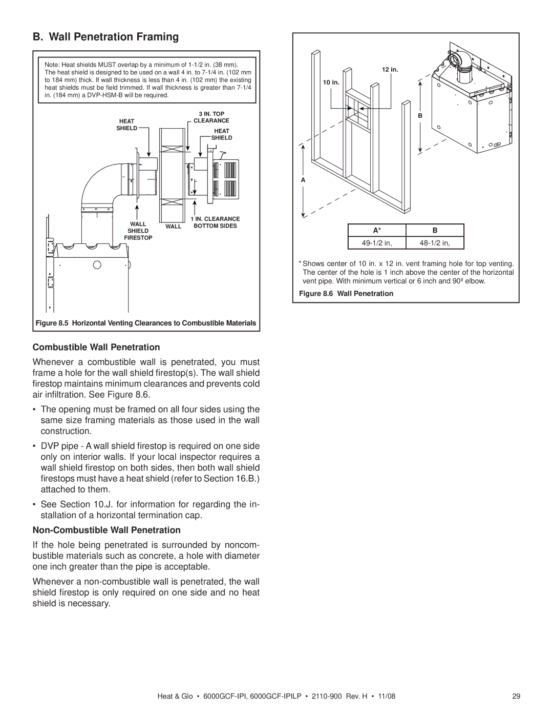
Whenever a combustible wall is penetrated, you must frame a hole for the wall shield firestop(s). The wall shield firestop maintains minimum clearances and prevents cold air infiltration. See Figure 8.6.
•The opening must be framed on all four sides using the same size framing materials as those used in the wall construction.
•DVP pipe - A wall shield firestop is required on one side only on interior walls. If your local inspector requires a wall shield firestop on both sides, then both wall shield firestops must have a heat shield (refer to Section 16.B.) attached to them.
•See Section 10.J. for information for regarding the in- stallation of a horizontal termination cap.
Non-Combustible Wall Penetration
If the hole being penetrated is surrounded by noncom- bustible materials such as concrete, a hole with diameter one inch greater than the pipe is acceptable.
Whenever a
12 in.
10 in.
B
A
A* | B |
*Shows center of 10 in. x 12 in. vent framing hole for top venting. The center of the hole is 1 inch above the center of the horizontal vent pipe. With minimum vertical or 6 inch and 90º elbow.
Figure 8.6 Wall Penetration
Heat & Glo • | 29 |