B. Vent Components Diagrams (continued)
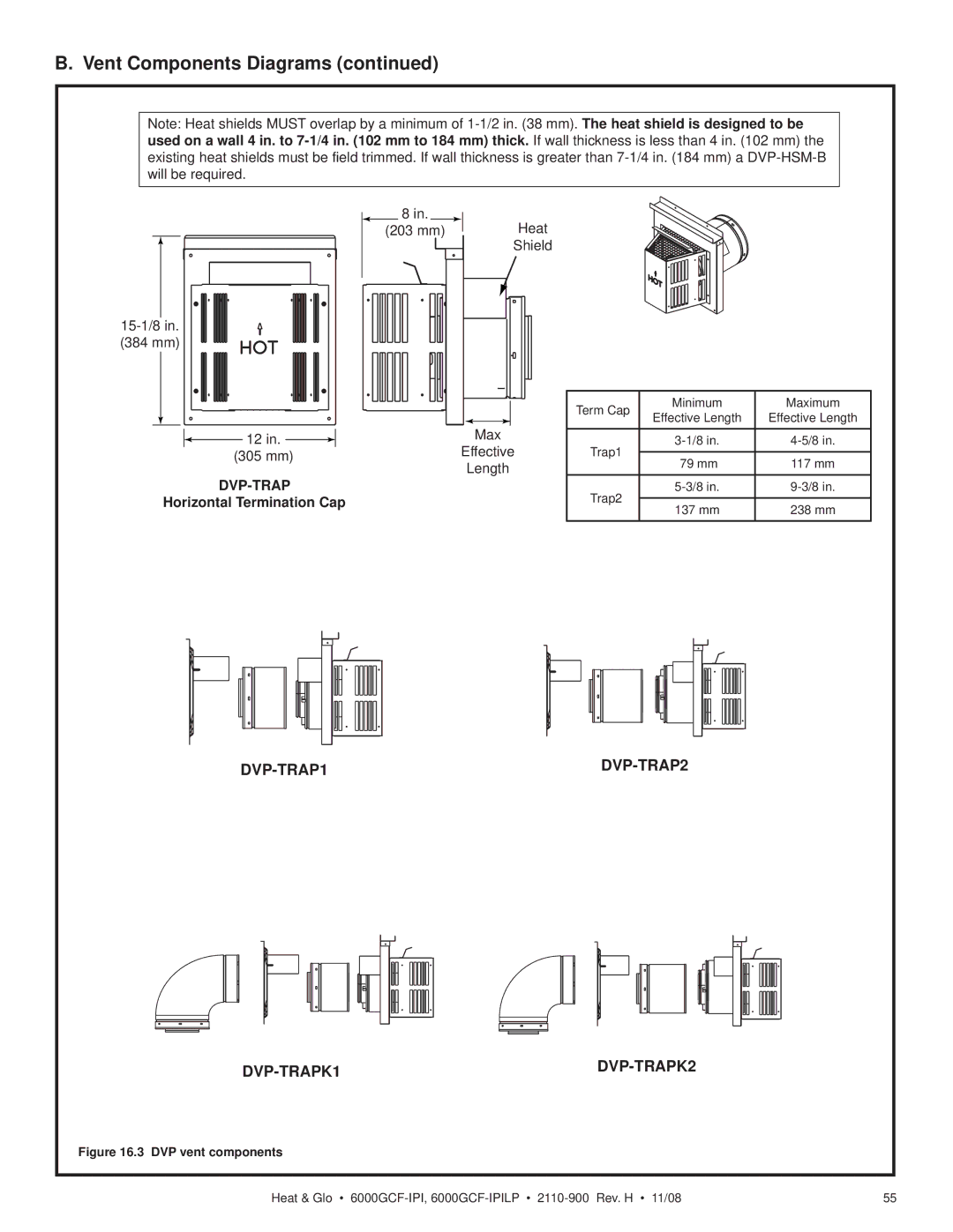
Note: Heat shields MUST overlap by a minimum of
8in.
(203 mm)
Heat
Shield
|
|
|
|
|
|
| ||||||||||
|
|
|
|
|
|
| ||||||||||
(384 mm) |
|
|
|
|
|
|
| |||||||||
|
|
|
|
|
|
|
|
|
|
|
|
|
|
|
|
|
|
|
|
|
|
|
|
|
|
|
|
|
|
| Term Cap | Minimum | Maximum |
|
|
|
|
|
|
|
|
|
|
|
|
|
| |||
|
|
|
|
|
|
|
|
|
|
|
|
|
| |||
|
|
|
|
|
|
|
|
|
|
|
|
|
| Effective Length | Effective Length | |
|
|
|
|
|
|
|
|
|
|
|
|
|
|
| ||
|
|
|
|
|
| 12 in. |
|
|
|
| Max |
|
| |||
|
|
|
|
|
|
|
|
|
|
|
|
|
| |||
|
|
|
|
|
|
|
|
|
|
|
| |||||
|
|
|
|
|
|
|
| |||||||||
|
|
|
|
| (305 mm) |
| Effective | Trap1 |
|
| ||||||
|
|
|
|
|
| 79 mm | 117 mm | |||||||||
|
|
|
|
|
| Length |
| |||||||||
|
|
|
|
|
|
|
|
| Trap2 | |||||||
|
| Horizontal Termination Cap |
|
|
|
|
|
| ||||||||
|
|
|
|
|
| 137 mm | 238 mm | |||||||||
|
|
|
|
|
|
|
|
|
|
|
|
|
|
| ||
|
|
|
|
|
|
|
|
|
|
|
|
|
|
|
|
|
Figure 16.3 DVP vent components
Heat & Glo • | 55 |