D. Electrical Service and Repair
WARNING! Risk of Shock! Label all wires prior to dis- connection when servicing controls. Wiring errors can cause improper and dangerous operation. Verify proper operation after servicing.
WARNING! Risk of Shock! Replace damaged wire with type 105º C rated wire. Wire must have high temperature insulation.
|
|
|
|
| I |
| INTERMITTENT |
| IGNITION MODULE |
|
| PILOT | |||
| 3 VAC |
|
|
| IGNITOR | ||
3V TRANSFORMER |
|
|
|
| |||
|
|
|
|
|
| ||
ON/OFF |
|
|
|
| S |
|
|
WALL |
|
|
|
|
|
|
|
SWITCH |
|
|
|
|
|
|
|
|
| FLAME SPARKER/ |
|
|
|
|
|
|
| SENSOR |
|
|
|
|
|
| IGNITION |
|
|
|
|
|
|
| MODULE |
|
|
|
|
|
|
| (3V) |
|
|
|
|
|
|
|
|
|
|
|
| WHT |
|
|
|
| BATTERY |
|
| ORG |
|
VALVE | LOW VOLTAGE |
| BLACK | * GROUND TO | |||
PACK |
| ||||||
|
| SEE NOTE 1 |
|
| FIREPLACE | ||
|
|
|
|
| |||
|
|
|
|
| CHASSIS | ||
|
| REMOTE |
| RED |
|
| |
NEUTRAL | GROUND | CONTROL HOT |
|
| BRN |
|
|
|
|
| BRN |
|
| ||
|
|
|
|
|
| ||
|
| WHITE WIRE |
|
|
|
|
|
|
| CAN BE |
|
|
| ORG |
|
|
| PLUGGED |
|
|
|
| |
|
| INTO ANY |
|
|
| GRN | |
BLACK WIRE CAN BE | OF |
|
| PIGGYBACK | |||
PLUGGED INTO ANY OF | LOCATIONS |
|
|
|
| ||
#1 - #5 LOCATIONS |
| ON THE |
|
| ON/OFF SWITCH |
|
|
ON THE HOT SIDE |
| NEUTRAL SIDE | TRANSFORMER |
|
|
|
|
|
|
| 3 VAC |
|
|
|
|
|
| PLUG IN |
|
|
|
| |
|
|
|
|
|
| VALVE |
|
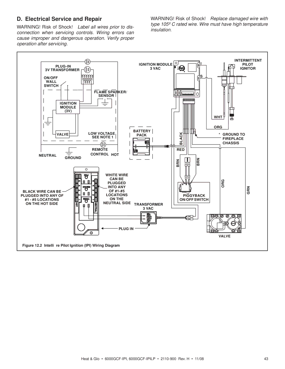
Figure 12.2 Intellifire Pilot Ignition (IPI) Wiring Diagram |
|
|
|
|
| ||
Heat & Glo • | 43 |