BV4236DBI specifications
The Hearth and Home Technologies BV4236DBI is a stunning direct vent gas fireplace that combines elegance with cutting-edge technology. Designed to enhance any living space, this fireplace provides a perfect blend of aesthetics and functionality, ensuring warmth and comfort during chilly evenings.One of the standout features of the BV4236DBI is its contemporary design that offers a wide viewing area for the mesmerizing flames. With a sleek front and minimalistic frame, it fits seamlessly into modern home decor, making it an attractive focal point in any room. The large, unobstructed glass allows for maximum visibility of the fire, providing a cozy ambiance.
Performance-wise, the BV4236DBI boasts an impressive heating capacity. With a BTU output of up to 36,000, it effectively warms spaces ranging from medium to large. The efficiency of this fireplace ensures not only warmth but also reduced energy costs, making it an economical choice.
The BV4236DBI features advanced venting technology that allows for installation flexibility. The direct vent design draws air from the outside for combustion, ensuring that indoor air quality remains unaffected. This setup minimizes heat loss and creates a safe environment for users, making it suitable for homes of all types.
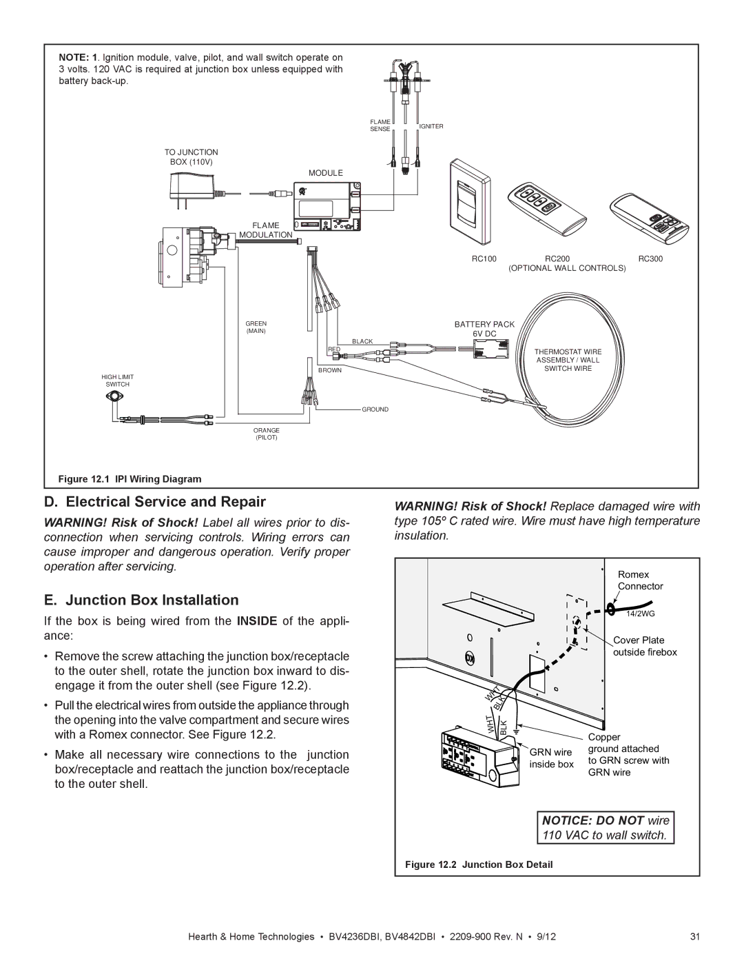
Another notable characteristic is the intuitive remote control and optional wall switch. This convenience feature allows users to easily adjust the flame height and heat output from anywhere in the room, ensuring customized comfort at the touch of a button. Additionally, the fireplace is equipped with an adjustable flame and media options, including decorative crushed glass or ceramic logs, which enhance the visual appeal.
Safety is a priority, and the BV4236DBI incorporates several safety features such as a built-in safety shutoff and an optional screen to prevent potential hazards. The fireplace's durable construction meets stringent safety standards, providing peace of mind for families.
In summary, the Hearth and Home Technologies BV4236DBI is a versatile, stylish, and efficient gas fireplace that offers an unmatched home heating experience. With its powerful performance, elegant design, and advanced technologies, it stands out as a prime choice for homeowners looking to elevate their living spaces with both comfort and sophistication. Whether for a cozy evening or a lively gathering, this fireplace provides the warmth and ambiance that every home deserves.

