RBV4236IT, RBV4842IT, RBV4842IH, RBV4236IH specifications
Hearth and Home Technologies has consistently combined aesthetic elegance with advanced technology in their range of contemporary fireplaces. Among their notable products are the RBV4236IH, RBV4842IH, RBV4842IT, and RBV4236IT models, each designed to enhance the ambiance of any living space while providing optimal heating solutions.The RBV4236IH is a 36-inch gas fireplace that exemplifies innovative design. This model is available in both direct vent and vent-free options, allowing users flexibility based on their installation needs. Its clean-face design provides a wide, unobstructed view of the flames, making it a captivating focal point in any room. Moreover, it features a modulating flame system that delivers consistent warmth while allowing users to customize the flame size for varying mood settings.
Moving to the RBV4842IH, this 42-inch model takes efficiency to new heights. It boasts an impressive heating capacity, suitable for larger spaces, and includes advanced flame technology that ensures realistic and visually striking flames. The RBV4842IH is equipped with adjustable media options, including glass and logs, providing versatility in styling to suit individual preferences.
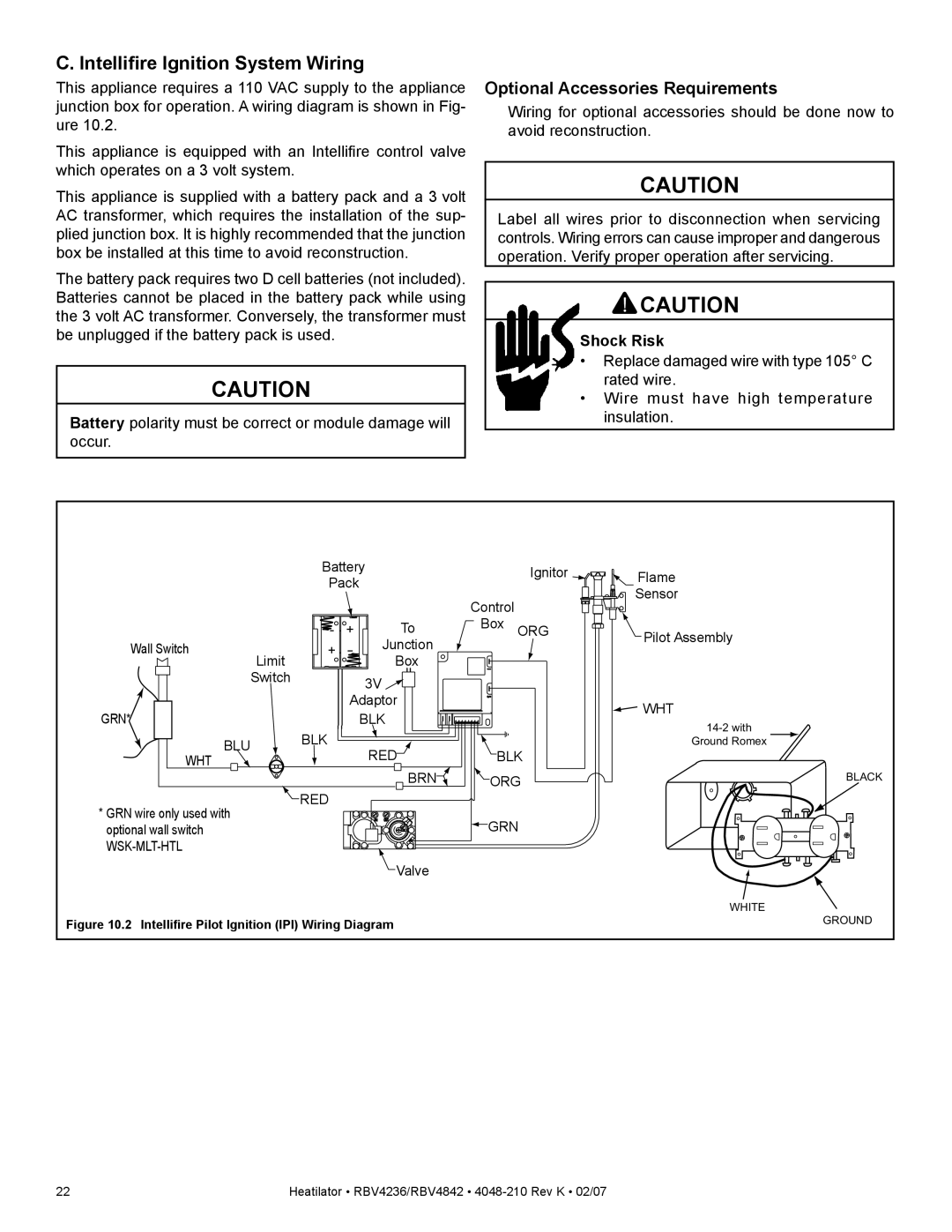
The RBV4842IT offers similar dimensions and features to the RBV4842IH, but it focuses on ease of installation and maintenance. With an innovative installation kit and design, homeowners can set up this fireplace with minimal hassle. It also incorporates a state-of-the-art ignition system, allowing for reliable starts every time, even during colder months.
Lastly, the RBV4236IT, also a 36-inch option, is tailored for versatile installations, including both residential and commercial spaces. It integrates high-efficiency heating technology that maximizes warmth while minimally impacting energy costs. Additionally, its user-friendly remote control provides ease in operation, making it simple to adjust settings without leaving the comfort of your seat.
In summary, Hearth and Home Technologies' RBV series represents a perfect blend of style, efficiency, and innovation. With thoughtfully designed features, including customizable flame settings, adjustable media, and smart ignition systems, these models cater to a wide audience, ensuring that both aesthetics and heating needs are met with excellence. Whether you're in search of a contemporary centerpiece for your home or an efficient heating solution, the RBV4236IH, RBV4842IH, RBV4842IT, and RBV4236IT models stand out as premier choices.

