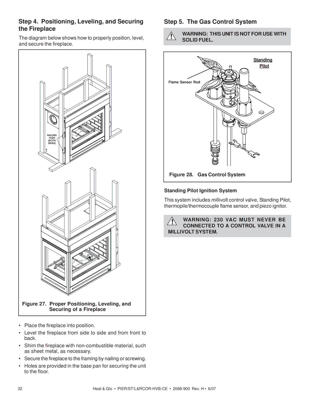
Step 4. Positioning, Leveling, and Securing the Fireplace
The diagram below shows how to properly position, level, and secure the fireplace.
NAILING |
TABS |
(BOTH |
SIDES) |
Figure 27. Proper Positioning, Leveling, and |
Securing of a Fireplace |
•Place the fireplace into position.
•Level the fireplace from side to side and from front to back.
•Shim the fireplace with
•Secure the fireplace to the framing by nailing or screwing.
•Holes are provided in the base pan for securing the unit to the floor.
Step 5. The Gas Control System
!WARNING: THIS UNIT IS NOT FOR USE WITH SOLID FUEL.
Standing
Pilot
Flame Sensor Rod
Figure 28. Gas Control System
Standing Pilot Ignition System
This system includes millivolt control valve, Standing Pilot, thermopile/thermocouple flame sensor, and piezo ignitor.
!WARNING: 230 VAC MUST NEVER BE CONNECTED TO A CONTROL VALVE IN A
MILLIVOLT SYSTEM.
32 | Heat & Glo • |