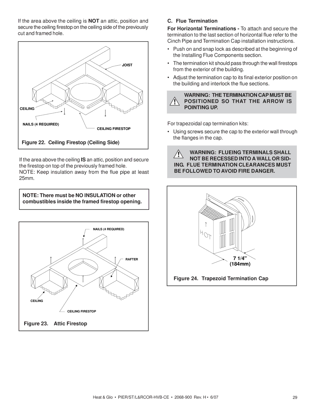
If the area above the ceiling is NOT an attic, position and secure the ceiling firestop on the ceiling side of the previously cut and framed hole.
JOIST |
CEILING |
NAILS (4 REQUIRED) |
CEILING FIRESTOP |
Figure 22. Ceiling Firestop (Ceiling Side) |
If the area above the ceiling IS an attic, position and secure the firestop on top of the previously framed hole.
NOTE: Keep insulation away from the flue pipe at least 25mm.
NOTE: There must be NO INSULATION or other combustibles inside the framed firestop opening.
| NAILS (4 REQUIRED) |
| RAFTER |
CEILING |
|
| CEILING FIRESTOP |
Figure 23. | Attic Firestop |
C. Flue Termination
For Horizontal Terminations - To attach and secure the termination to the last section of horizontal flue refer to the Cinch Pipe and Termination Cap installation instructions.
•Push on and snap lock as described at the beginning of the Installing Flue Components section.
•The termination kit should pass through the wall firestops from the exterior of the building.
•Adjust the termination cap to its final exterior position on the building and interlock the flue sections.
WARNING: THE TERMINATION CAP MUST BE
!POSITIONED SO THAT THE ARROW IS POINTING UP.
For trapezoidal cap termination kits:
•Using screws secure the cap to the exterior wall through the flanges in the cap.
!WARNING: FLUEING TERMINALS SHALL NOT BE RECESSED INTO A WALL OR SID-
ING. FLUE TERMINATION CLEARANCES MUST BE FOLLOWED TO AVOID FIRE DANGER.
7 1/4" (184mm)
Figure 24. Trapezoid Termination Cap
Heat & Glo • | 29 |