B. Constructing the Appliance Chase
A chase is a vertical
NOTICE: Treatment of ceiling firestops and wall shield firestops and construction of the chase may vary with the type of building. These instructions are not substitutes for the requirements of local building codes. Therefore, you MUST check local building codes to determine the requirements to these steps.
Chases should be constructed in the manner of all out- side walls of the home to prevent cold air drafting prob- lems. The chase should not break the outside building envelope in any manner.
Walls, ceiling, base plate and cantilever floor of the chase should be insulated. Vapor and air infiltration barriers should be installed in the chase as per regional codes for the rest of the home. Additionally, in regions where cold air infiltration may be an issue, the inside surfaces may be sheetrocked and taped for maximum air tightness.
To further prevent drafts, the wall shield and ceiling fire- stops should be caulked with high temperature caulk to seal gaps. Gas line holes and other openings should be caulked with high temp caulk or stuffed with unfaced in- sulation. If the appliance is being installed on a cement slab, a layer of plywood may be placed underneath to prevent conducting cold up into the room.
C. Clearances
NOTICE: Install appliance on hard metal or wood surfaces extending full width and depth. DO NOT install directly on carpeting, vinyl, tile or any combustible material other than wood.
WARNING! Risk of Fire! Maintain specified air space clearances to appliance and vent pipe:
•Insulation and other materials must be secured to prevent accidental contact.
•The chase must be properly blocked to prevent blown insulation or other combustibles from entering and making contact with fireplace or chimney.
•Failure to maintain airspace may cause overheating and a fire.
A
A
HEADER
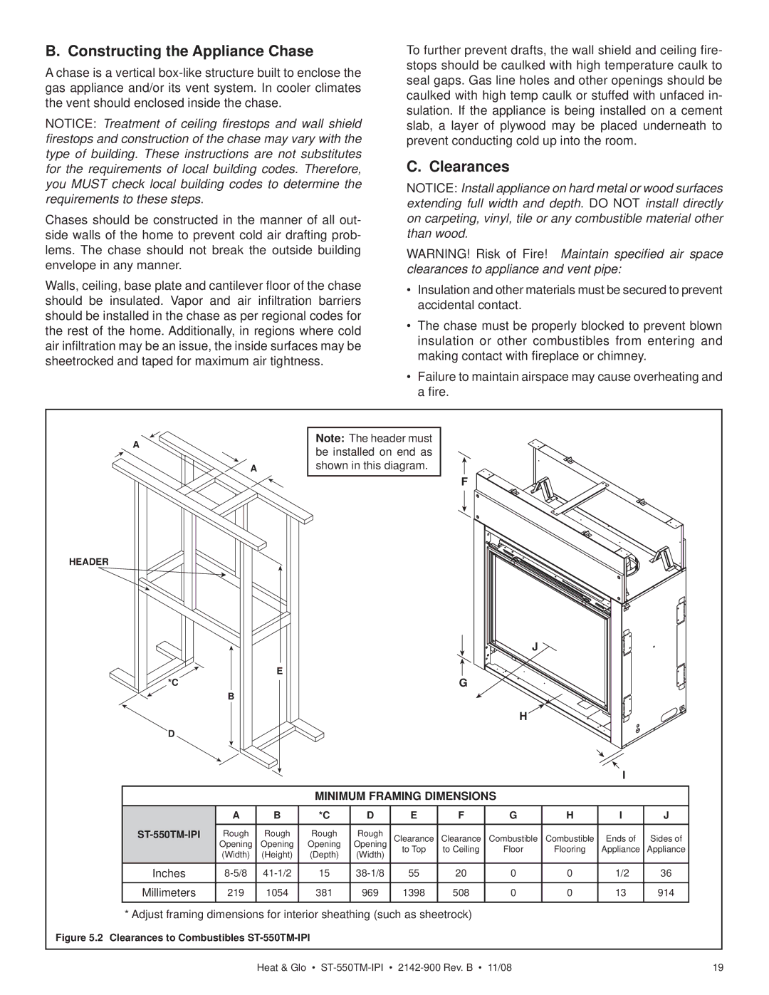
Note: The header must be installed on end as shown in this diagram.
F
|
|
|
|
|
|
| J |
|
|
|
*C |
| E |
|
|
| G |
|
|
|
|
B |
|
|
|
|
|
|
|
| ||
|
|
|
|
|
|
|
|
|
| |
|
|
|
|
|
|
| H |
|
|
|
D |
|
|
|
|
|
|
|
|
|
|
|
|
|
|
|
|
|
|
| I |
|
|
|
| MINIMUM FRAMING DIMENSIONS |
|
|
| ||||
| A | B | *C | D | E | F | G | H | I | J |
| Rough | Rough | Rough | Rough | Clearance | Clearance | Combustible | Combustible | Ends of | Sides of |
| Opening | Opening | Opening | Opening | ||||||
| (Width) | (Height) | (Depth) | (Width) | to Top | to Ceiling | Floor | Flooring | Appliance | Appliance |
|
|
|
|
|
|
| ||||
Inches | 15 | 55 | 20 | 0 | 0 | 1/2 | 36 | |||
Millimeters | 219 | 1054 | 381 | 969 | 1398 | 508 | 0 | 0 | 13 | 914 |
* Adjust framing dimensions for interior sheathing (such as sheetrock)
Figure 5.2 Clearances to Combustibles ST-550TM-IPI
Heat & Glo • | 19 |