BW36 SERIES WOODBURNING FIREPLACE
No one builds a better fire
F. STEP-BY-STEP INSTALLATION OF THE FIREPLACE SYSTEM
WARNING!
BEFORE STARTING, DO THE FOLLOWING:
1.WEAR GLOVES AND SAFETY GLASSES FOR PROTECTION.
2.KEEP HAND TOOLS IN GOOD CONDITION. SHARPEN CUTTING EDGES AND MAKE SURE TOOL HANDLES ARE SECURE.
3.ALWAYS MAINTAIN THE MINIMUM AIR SPACE REQUIRED TO THE ENCLOSURE TO PREVENT FIRE.
STEP 1 - Positioning the Fireplace.
This fireplace may be placed on either a combustible or
STEP 2 - Placing the Protective Metal Hearth Strips.
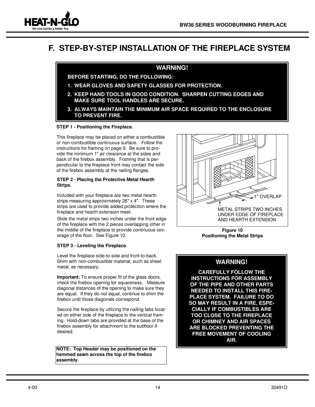
Included with your fireplace are two metal hearth strips measuring approximately 26" x 4". These strips are used to provide added protection where the fireplace and hearth extension meet.
Slide the metal strips two inches under the front edge of the fireplace with the 2 pieces overlapping other in the middle of the fireplace to provide continuous cov- erage of the floor. See Figure 10.
STEP 3 - Leveling the Fireplace.
Level the fireplace
Important: To ensure proper fit of the glass doors, check the firebox opening for squareness. Measure diagonal distances of the opening to make sure they are equal. If they do not equal, continue to shim the firebox until those diagonals correspond.
Secure the fireplace by utilizing the nailing tabs locat- ed on either side of the fireplace to the vertical fram- ing.
NOTE: Top Header may be positioned on the hemmed seam across the top of the firebox assembly.
![]() 1" OVERLAP
1" OVERLAP
METAL STRIPS TWO INCHES
UNDER EDGE OF FIREPLACE
AND HEARTH EXTENSION
Figure 10
Positioning the Metal Strips
WARNING!
CAREFULLY FOLLOW THE
INSTRUCTIONS FOR ASSEMBLY OF THE PIPE AND OTHER PARTS NEEDED TO INSTALL THIS FIRE- PLACE SYSTEM. FAILURE TO DO SO MAY RESULT IN A FIRE, ESPE-
CIALLY IF COMBUSTIBLES ARE TOO CLOSE TO THE FIREPLACE OR CHIMNEY AND AIR SPACES ARE BLOCKED PREVENTING THE FREE MOVEMENT OF COOLING AIR.
14 | 30491D |