BW36 SERIES WOODBURNING FIREPLACE
No one builds a better fire
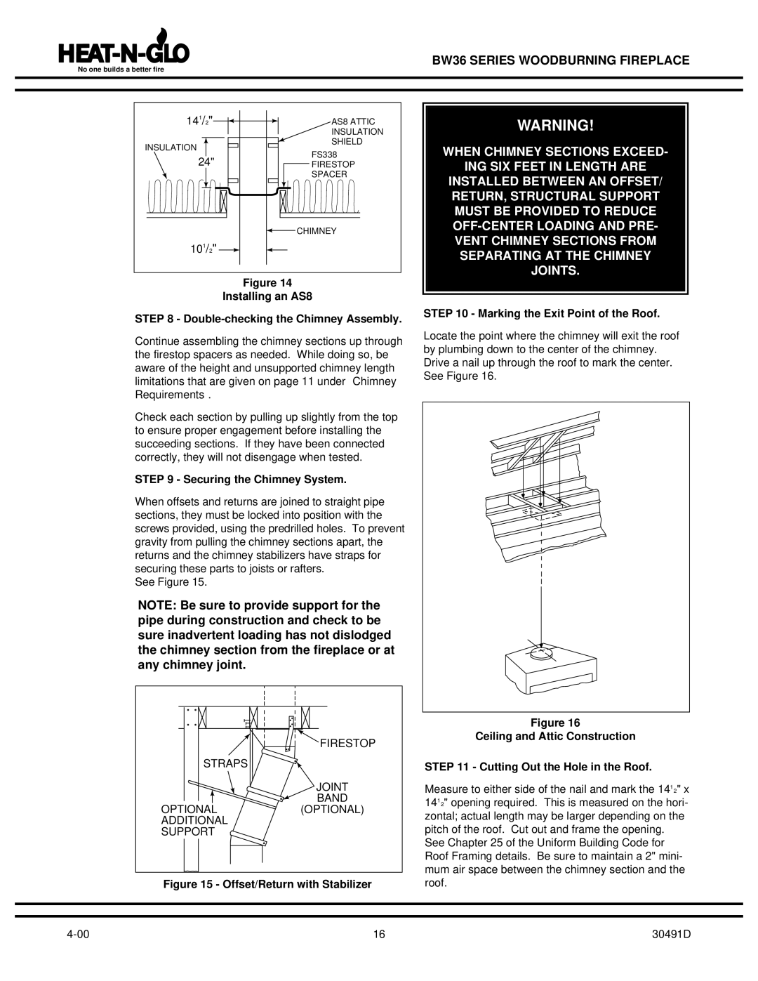
141/2" | AS8 ATTIC | |
| INSULATION | |
INSULATION | SHIELD | |
FS338 | ||
24" | ||
FIRESTOP | ||
| SPACER | |
| CHIMNEY | |
101/2" |
|
Figure 14
Installing an AS8
STEP 8 - Double-checking the Chimney Assembly.
Continue assembling the chimney sections up through the firestop spacers as needed. While doing so, be aware of the height and unsupported chimney length limitations that are given on page 11 under “Chimney Requirements”.
Check each section by pulling up slightly from the top to ensure proper engagement before installing the succeeding sections. If they have been connected correctly, they will not disengage when tested.
STEP 9 - Securing the Chimney System.
When offsets and returns are joined to straight pipe sections, they must be locked into position with the screws provided, using the predrilled holes. To prevent gravity from pulling the chimney sections apart, the returns and the chimney stabilizers have straps for securing these parts to joists or rafters.
See Figure 15.
NOTE: Be sure to provide support for the pipe during construction and check to be sure inadvertent loading has not dislodged the chimney section from the fireplace or at any chimney joint.
WARNING!
WHEN CHIMNEY SECTIONS EXCEED-
ING SIX FEET IN LENGTH ARE
INSTALLED BETWEEN AN OFFSET/ RETURN, STRUCTURAL SUPPORT MUST BE PROVIDED TO REDUCE
STEP 10 - Marking the Exit Point of the Roof.
Locate the point where the chimney will exit the roof by plumbing down to the center of the chimney. Drive a nail up through the roof to mark the center. See Figure 16.
FIRESTOP
STRAPS
JOINT
BAND
OPTIONAL(OPTIONAL)
ADDITIONAL
SUPPORT
Figure 15 - Offset/Return with Stabilizer
16 |
Figure 16
Ceiling and Attic Construction
STEP 11 - Cutting Out the Hole in the Roof.
Measure to either side of the nail and mark the 141⁄2" x 141⁄2" opening required. This is measured on the hori- zontal; actual length may be larger depending on the pitch of the roof. Cut out and frame the opening.
See Chapter 25 of the Uniform Building Code for Roof Framing details. Be sure to maintain a 2" mini- mum air space between the chimney section and the roof.
30491D