2. Continue Adding Vent Components

Refer to Cinch Pipe and Termination Cap installation in- structions.

Continue adding vent components, locking each succeed- ing component into place.

Ensure that each succeeding vent component is secure- ly fitted and locked into the preceding component in the vent system. Securing pipe sections with a maximum of two screws is recommended.

90° elbows may be installed and rotated to any point around the preceding component’s vertical axis. If an el- bow does not end up in a locked position with the pre- ceding component, attach with a minimum of two (2) sheet metal screws.

3.Install Support Brackets

Refer to Cinch Pipe and Termination Cap installation in- structions.

4. Install Firestops

For Horizontal Runs - Firestops are REQUIRED on both sides of a combustible wall through which the vent passes.

NOTE: Model DVP-TRAP does not need an exterior fir- estop on an exterior combustible wall. The firestop is built into the cap.

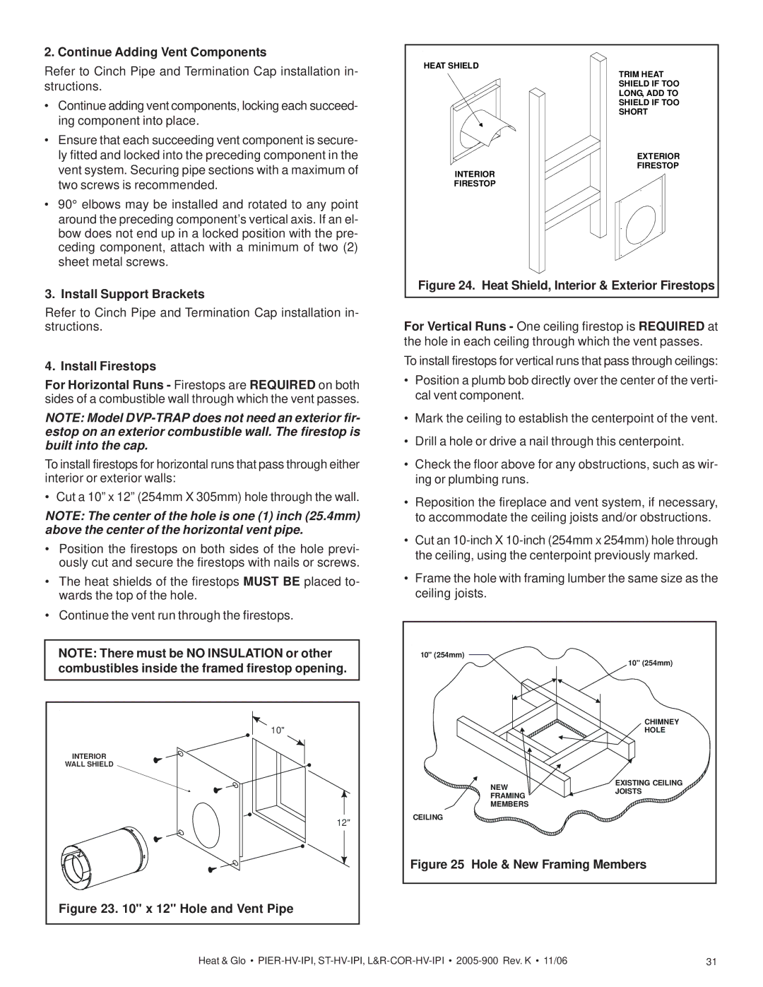
To install firestops for horizontal runs that pass through either interior or exterior walls:

• Cut a 10” x 12” (254mm X 305mm) hole through the wall.

NOTE: The center of the hole is one (1) inch (25.4mm) above the center of the horizontal vent pipe.

Position the firestops on both sides of the hole previ- ously cut and secure the firestops with nails or screws.

The heat shields of the firestops MUST BE placed to- wards the top of the hole.

Continue the vent run through the firestops.

NOTE: There must be NO INSULATION or other combustibles inside the framed firestop opening.

10"

INTERIOR

WALL SHIELD

12"

Figure 23. 10" x 12" Hole and Vent Pipe

HEAT SHIELD

TRIM HEAT SHIELD IF TOO LONG, ADD TO SHIELD IF TOO SHORT

EXTERIOR

FIRESTOP

INTERIOR

FIRESTOP

Figure 24. Heat Shield, Interior & Exterior Firestops

For Vertical Runs - One ceiling firestop is REQUIRED at the hole in each ceiling through which the vent passes.

To install firestops for vertical runs that pass through ceilings:

Position a plumb bob directly over the center of the verti- cal vent component.

Mark the ceiling to establish the centerpoint of the vent.

Drill a hole or drive a nail through this centerpoint.

Check the floor above for any obstructions, such as wir- ing or plumbing runs.

Reposition the fireplace and vent system, if necessary, to accommodate the ceiling joists and/or obstructions.

Cut an 10-inch X 10-inch (254mm x 254mm) hole through the ceiling, using the centerpoint previously marked.

Frame the hole with framing lumber the same size as the ceiling joists.

10" (254mm)

10" (254mm)


CHIMNEY


HOLE

NEW

EXISTING CEILING

JOISTS

FRAMING


MEMBERS


CEILING


Figure 25 Hole & New Framing Members

Heat & Glo • PIER-HV-IPI, ST-HV-IPI, L&R-COR-HV-IPI2005-900 Rev. K • 11/06

31

Page 31
Image 31
Heat & Glo LifeStyle PIER-HV-IPI, LCOR-HV-IPI, ST-HV-IPI Continue Adding Vent Components, Install Support Brackets

PIER-HV-IPI, ST-HV-IPI, RCOR-HV-IPI, LCOR-HV-IPI specifications

The Heat & Glo LifeStyle series, which includes models like the ST-HV-IPI, RCOR-HV-IPI, PIER-HV-IPI, and LCOR-HV-IPI, represents a significant advancement in modern fireplace technology, offering both aesthetic appeal and efficient heating solutions. These models are designed to enhance the beauty and comfort of any living space, merging functional innovation with sophisticated design.

One of the standout features of the LifeStyle series is the inclusion of the Instant Ignition, also known as IPI technology. This allows for quick and effortless lighting of the fireplace, providing immediate warmth and ambiance. With a simple push of a button, users can enjoy the soothing glow of flames without the hassle of matches or kindling. This feature is particularly appreciated during unexpected chilly evenings when you want to create a cozy atmosphere in an instant.

In terms of efficiency, all models in the LifeStyle series utilize advanced venting technologies, which ensure that heat is directed effectively into the living space while maximizing fuel efficiency. The linear design options combined with versatile venting configurations allow homeowners to install these fireplaces in various locations, making them adaptable for different room layouts and styles.

The aesthetic appeal of the LifeStyle fireplaces is heightened by customizable options. Users can choose from a wide array of face options, styles, and finishes to match their home décor. The glass viewing area is designed to be expansive, providing a warm and inviting view of the flames, while the clean, contemporary lines of the units make them suitable for both modern and traditional interiors.

Moreover, the LifeStyle series is equipped with remote control features that enhance user convenience. Homeowners can easily adjust flame height, heat output, and lighting without leaving the comfort of their seating area.

Safety is another crucial aspect of the LifeStyle series. The fireplaces include safety components such as an automatic shut-off that activates under certain conditions, providing peace of mind for families with children or pets.

Overall, the Heat & Glo LifeStyle ST-HV-IPI, RCOR-HV-IPI, PIER-HV-IPI, and LCOR-HV-IPI models epitomize modern fireplace design, combining efficiency and style with advanced technology and user-friendly features, making them a perfect choice for anyone looking to enhance their home environment.