Heat & Glo LifeStyle SLR-C (COSMO) B. Vent Components Diagrams continued, 15-1/2IN 394 mm, SLP90

Models: SLR-C (COSMO)

1 71
Download 71 pages 48.08 Kb
Page 65
Image 65
SLP-HRC-SS

B. Vent Components Diagrams (continued)

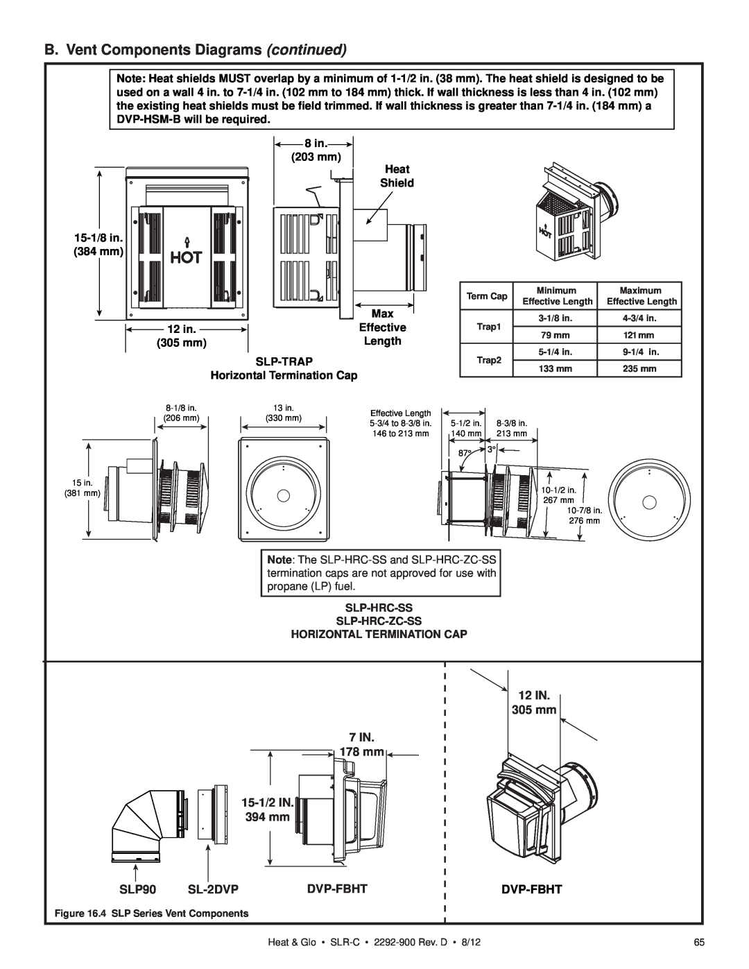
Note: Heat shields MUST overlap by a minimum of 1-1/2 in. (38 mm). The heat shield is designed to be used on a wall 4 in. to 7-1/4 in. (102 mm to 184 mm) thick. If wall thickness is less than 4 in. (102 mm) the existing heat shields must be field trimmed. If wall thickness is greater than 7-1/4 in. (184 mm) a DVP-HSM-B will be required.

HORIZONTAL TERMINATION CAP 8 in.15-1/2 IN. (203 mm)

Heat

Shield

15-1/8 in.

(384 mm)


Max

12 in.


Effective

(305 mm)


Length


SLP-TRAP


Horizontal Termination Cap


8-1/8 in.

13 in.

Effective Length

(206 mm)

(330 mm)

5-3/4 to 8-3/8 in.


146 to 213 mm

15 in.

(381 mm)

Term Cap


Minimum

Maximum

Effective Length

Effective Length


Trap1


3-1/8 in.

4-3/4 in.


79 mm

121 mm


Trap2


5-1/4 in.

9-1/4 in.


133 mm

235 mm


5-1/2 in.

8-3/8 in.


140 mm

213 mm


87°


10-1/2 in.


267 mm


10-7/8 in.


276 mm


Note: The SLP-HRC-SS and SLP-HRC-ZC-SS termination caps are not approved for use with propane (LP) fuel.

SLP-HRC-SS

SLP-HRC-ZC-SS

HORIZONTAL TERMINATION CAP

15-1/2 IN.

394 mm

7 IN.

178 mm 7 IN.

12IN.

305mm

SLP90

SL-2DVP

DVP-FBHT

DVP-FBHT

Figure 16.4 SLP Series Vent Components

Heat & Glo • SLR-C2292-900 Rev. D • 8/12

65

Page 65
Image 65
Heat & Glo LifeStyle SLR-C (COSMO) B. Vent Components Diagrams continued, 15-1/2IN 394 mm, 7 IN 178 mm, 12IN 305mm, SLP90