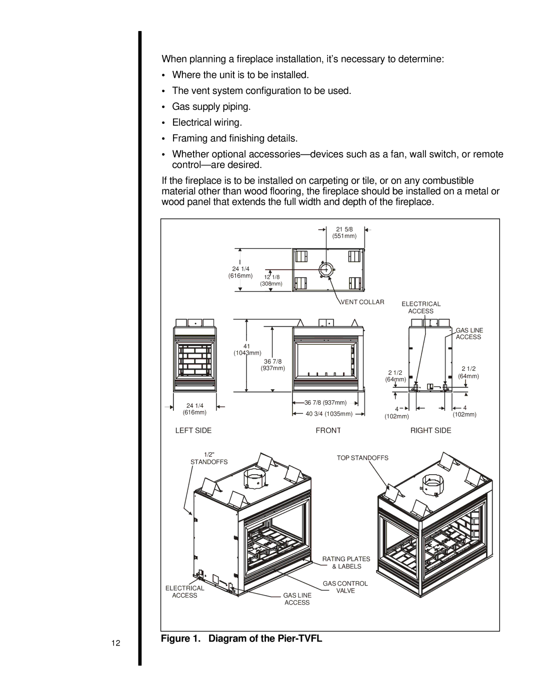
st-42tvfl specifications
The Heat & Glo LifeStyle ST-42TVFL is a premier gas fireplace that seamlessly combines modern design with advanced technology, providing an optimal heating experience for homes. With its clean lines and stylish aesthetics, this fireplace not only serves as a functional source of warmth but also enhances the ambiance of any living space.One of the standout features of the ST-42TVFL is its impressive viewing area. The large, front-facing glass provides an unobstructed view of the dancing flames, creating a focal point in the room that captivates and engages. The fireplace is equipped with a sleek, contemporary design, featuring a linear burner that produces a beautiful flame pattern, enhancing the visual appeal.
In terms of technology, the LifeStyle ST-42TVFL incorporates advanced Heat & Glo innovation with the IntelliFire touch ignition system, which allows for easy and reliable operation. This system ensures that the fireplace ignites efficiently with the simple push of a button, eliminating the need for matches or lighters. For added convenience, the fireplace can also be operated with a remote control, allowing users to adjust the flame height and turn the unit on or off from anywhere in the room.
The ST-42TVFL is designed with energy efficiency in mind. It boasts a direct venting system that draws air from the outside for combustion, ensuring that indoor air quality is maintained. This feature also maximizes heating efficiency, providing warmth without sacrificing comfort or safety. The fireplace has an impressive thermal efficiency rating, making it an eco-friendly choice for homeowners looking to reduce their carbon footprint while enjoying a cozy atmosphere.
Another noteworthy characteristic of the Heat & Glo LifeStyle ST-42TVFL is its customizable options. Users can select from a variety of interior finishes, media options, and decorative surrounds, allowing for personalized integration with any home decor. Whether a sleek modern design or a more traditional aesthetic is desired, this fireplace can be tailored to fit individual tastes.
In summary, the Heat & Glo LifeStyle ST-42TVFL gas fireplace is a sophisticated heating solution that offers a combination of style, efficiency, and advanced technology. Its expansive viewing area, intelligent ignition system, and customizable design make it a popular choice for homeowners seeking both form and function in their living spaces. With its focus on energy efficiency and user-friendly features, the ST-42TVFL stands out as an exceptional choice for enhancing any home.

