Air Conditioning/Heat Pump
Only for authorized service personnel
HEAT CONTROLLER, INC
Wall Mounted Mini-SplitSystem Single-Zone
TABLE OF CONTENTS
2Room Air Conditioner
Be sure not to do
Safety Precautions
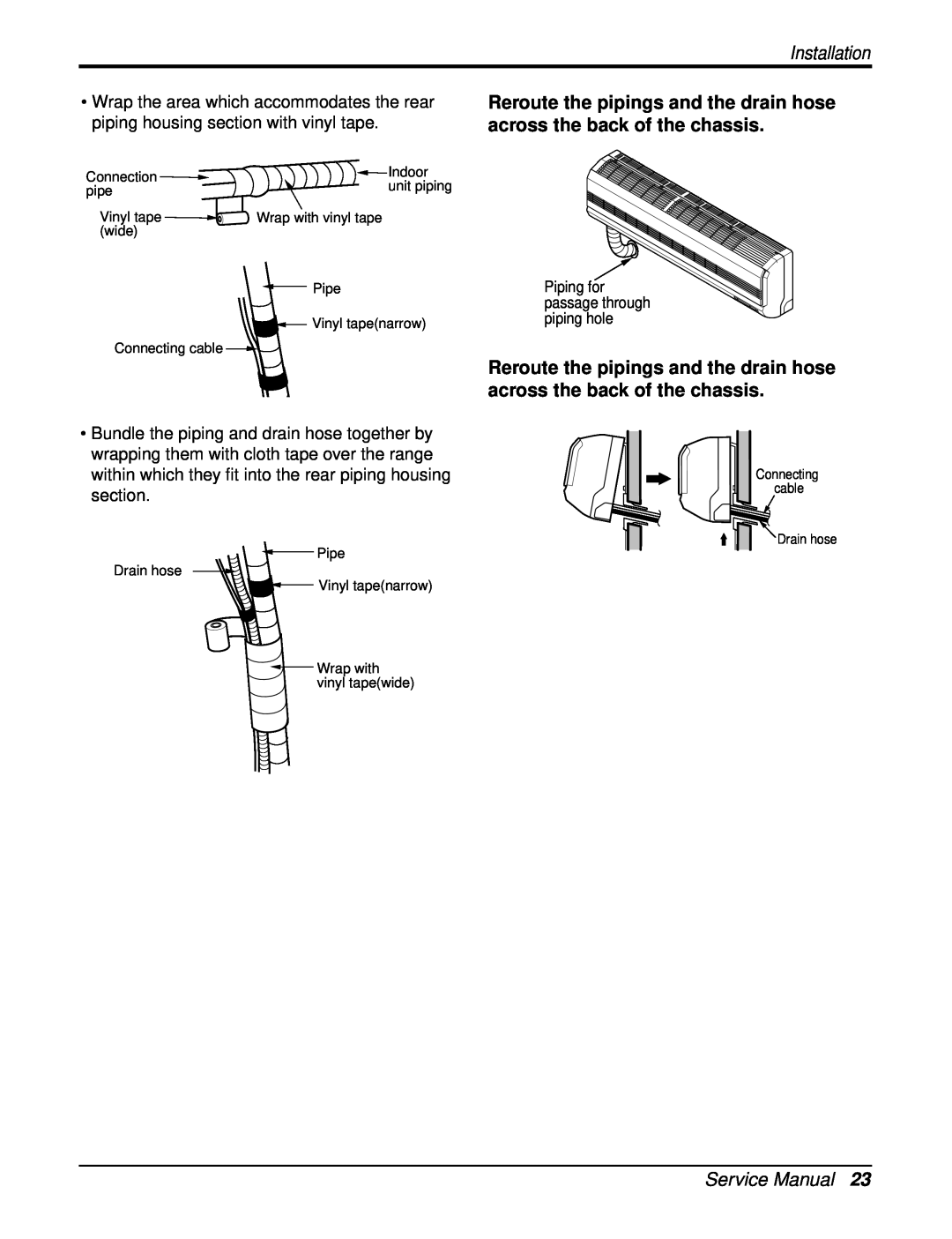
Installation
Safety Precautions
Do not handle the pipe by your- selfCostomer
Operation
4Room Air Conditioner
Safety Precautions
There is risk of electrical shock
Safety Precautions
There is risk of fire or electrical shock
There is risk of electric shock
Install the drain hose to ensure that
6Room Air Conditioner
Installation
Safety Precautions
Do not use harsh detergents, sol- vents, etc
Disuse
Safety Precautions
Use a soft cloth to clean
8Room Air Conditioner
Dimensions
Dimensions
IndoorUnit
Model
Dimensions
Dimensions
OutdoorUnit
1. 9k, 12k
10Room Air Conditioner
Dimensions
2. 18k, 24k
Introduction
SymbolsUsedIn ThisManual
Features
NOTICE This symbol indicates special notes
Introduction
Installation
Installation Parts
InstallationTools
14Room Air Conditioner
InstallationMap
Installation
THIS PRODUCT CONTAINS R-410AREFRIGERANT
ConfirmTheRefrigerant
Installation
Outdoor unit
Rooftop Installations
SelectTheBest Location
Indoor unit
Installation
PipingLengthAndElevation
Installation
How To Mount Installation Plate
DrillaHoleIn The Wall
18Room Air Conditioner
Putting nut on
Flaring Work
Cut the pipes and the cable
Burrs removal
For left rear piping
ConnectingThePiping
Indoor unit installation
Indoor
Installation
For right rear piping
Installation
Insert the connecting cable into the indoor unit
Indoor unit installation
22Room Air Conditioner
Piping for passage through piping hole
Installation
Installation
Correct case
Incorrect case
24Room Air Conditioner
the face of the flare before assembling
ConnectionOfTheDrainHose
ConnectionOfPiping-Outdoor
Put a couple drops of refrigerant oil on
7.Use lock nuts to secure the conduit tubes
ConnectionOfTheCable
2.Dismount caps on the conduit panel
5.Ground the unit in accordance with local codes
8The following would be caused by voltage drop
Installation
3Specification of power source
4Confirm that electrical capacity is sufficient
Installation
CheckingTheDrainage
Drain piping
28Room Air Conditioner
Installation
FormingThePiping
Leak test
AirPurging
Airpurging With Vacuum Pump
Preparation
Installation
Evacuation
Finishing the job
Installation
Charging
Important Unit is critically charged
32Room Air Conditioner
Evaluation of the performance
Prepare remote control
Test Running
Settlement of outdoor unit
DISPLAY
Operation
FunctionofControls
Operation
Operation
Heating Mode Operation
Defrost Control
Jet Cool Mode Operation C/O Model
Sleep Timer Operation
Airflow Speed Selection
Chaos Natural Wind Mode
Protection of the evaporator pipe from frosting
Forced operation
Test operation
Auto restart
38Room Air Conditioner
Display Function
Self-diagnosisFunction
1. Heating Model
9.TIMER SET/CANCEL BUTTON
RemoteControlOperations
7.ON/OFF TIMER BUTTONS
8.TIME SETTING BUTTONS
Operation
Disassembly
Indoor Unit
40Room Air Conditioner
4.To remove the Evaporator
Disassembly
2. To remove the Control Box
3.To remove the Discharge Grille
6.To remove the Cross-FlowFan
Disassembly
42Room Air Conditioner
5.To remove the Motor Cover
1 Cooling Only Models
Troubleshooting Guide
RefrigerationCycleDiagram
Troubleshooting Guide
2-wayValve Liquid Side
2-way,3-wayValve
44Room Air Conditioner
Troubleshooting Guide
2Operate the unit for 10 to 15 minutes
Procedure
Pumping Down
Troubleshooting Guide
Procedure
Balance Refrigerant of the 3-wayValve
46Room Air Conditioner
Troubleshooting Guide
All amount of refrigerant leaked
Troubleshooting Guide
Procedure
Evacuation
Procedure
Gas Charging
48Room Air Conditioner
Troubleshooting Guide
Additional gas charging
The method of using graph
The method of using equation
According to Indoor & Outdoor Temperature
Troubleshooting Guide
CycleParts
Trouble analysis
50Room Air Conditioner
Troubleshooting Guide
ElectronicParts9kmodel
Product does not operate at all
Product does not operate at all
ElectronicParts18k model
52Room Air Conditioner
Troubleshooting Guide
Turn on Main Power
Troubleshooting Guide
Troubleshooting Guide
54Room Air Conditioner
Turn on Main Power
Troubleshooting Guide
Troubleshooting Guide
When indoor Fan does not operate
56Room Air Conditioner
Troubleshooting Guide
When Vertical Louver does not operate
Troubleshooting Guide
When a comunication error occurs
58Room Air Conditioner
Troubleshooting Guide
The phenomena in case of connecting error
INDOOR UNIT
Troubleshooting Guide
OUTDOOR UNIT
60Room Air Conditioner
Indoor
Schematic Diagram
Schematic Diagram
ElectricControl Device
Schematic Diagram
Outdoor 9k, 12k
62Room Air Conditioner
Schematic Diagram
Outdoor 18k, 24k
Schematic Diagram
Wiring Diagram
Indoor Unit
64Room Air Conditioner
Schematic Diagram
Outdoor Unit
Models 9kC/O
Models 12kH/P, 12kC/O, H/P
Schematic Diagram
Models 18kC/O
Models 18kH/P, 24kC/O, H/P
66Room Air Conditioner
Schematic Diagram
Indoor MAIN P.W.B ASSEMBLY TOP VIEW
ComponentsLocation
BOTTOM VIEW
Schematic Diagram
Outdoor9k, 12k TOP VIEW BOTTOM VIEW
68Room Air Conditioner
Schematic Diagram
Outdoor18k, 24k TOP VIEW BOTTOM VIEW
Schematic Diagram
DISPLAY ASSEMBLY
6870A90240D - 6870A90240E
70Room Air Conditioner
Model Name
Product Specifications
Product Specifications
Cooling Only
Product Specifications
Cooling & Heating
72Room Air Conditioner
THE QUALITY LEADER IN CONDITIONING AIR
HEAT CONTROLLER, INC
1900 WELLWORTH AVENUE JACKSON, MICHIGAN