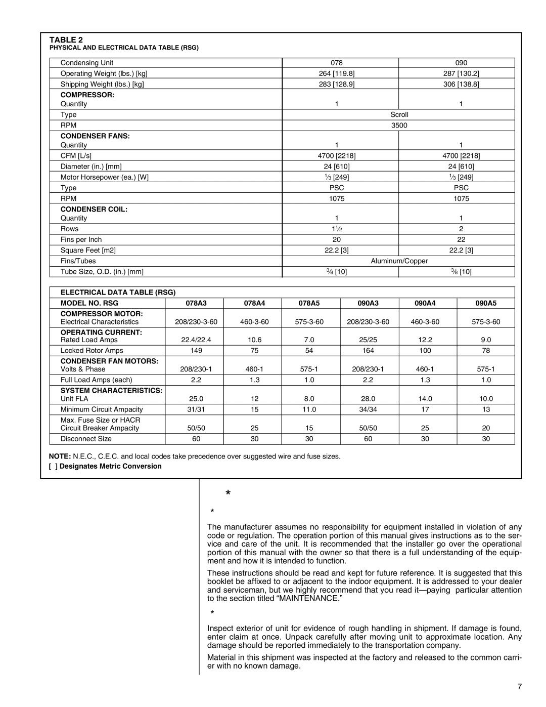
R-410A specifications
The Heat Controller R-410A is an advanced refrigerant used in various heating and cooling applications, particularly in residential and commercial air conditioning systems. Recognized for its efficiency and eco-friendliness, R-410A has become a popular choice among HVAC manufacturers and professionals.One of the main features of R-410A is its high efficiency. It operates at a higher pressure than traditional refrigerants, which allows it to transfer heat more effectively. This results in improved energy efficiency ratings (SEER and EER) for systems utilizing R-410A, leading to lower energy bills and reduced environmental impact.
R-410A is also known for its environmental sustainability. Unlike its predecessor, R-22, R-410A has zero ozone depletion potential (ODP) due to its composition of hydrofluorocarbons (HFCs). Although it does have a global warming potential (GWP), the advancements in technology have made R-410A a more environmentally friendly option compared to many older refrigerants.
Developed through innovative technological advancements, R-410A systems often incorporate variable speed compressors and efficient heat exchangers. These technologies allow for better modulation of cooling and heating outputs, ensuring that the indoor environment remains comfortable while using the least amount of energy possible.
Another significant characteristic of R-410A is its compatibility with a wide range of HVAC equipment. Many new air conditioning systems are designed specifically to use R-410A, which has led to the creation of a robust market for these units. Additionally, R-410A systems tend to require less maintenance and have longer lifespans compared to those using older refrigerants.
Safety is another consideration for R-410A users. While R-410A is non-toxic and non-flammable, technicians who work with this refrigerant need to be trained and certified due to its high-pressure properties. Proper handling and installation are crucial to ensure system efficiency and reliability.
In summary, the Heat Controller R-410A stands out in the HVAC industry for its efficiency, environmental benefits, advanced technologies, and compatibility with modern systems. As the industry continues to evolve, R-410A remains a key player, paving the way towards more sustainable and efficient heating and cooling solutions.

