4 | Getting Started | Installer Guide |
| ||
|
|
A. Typical Appliance System
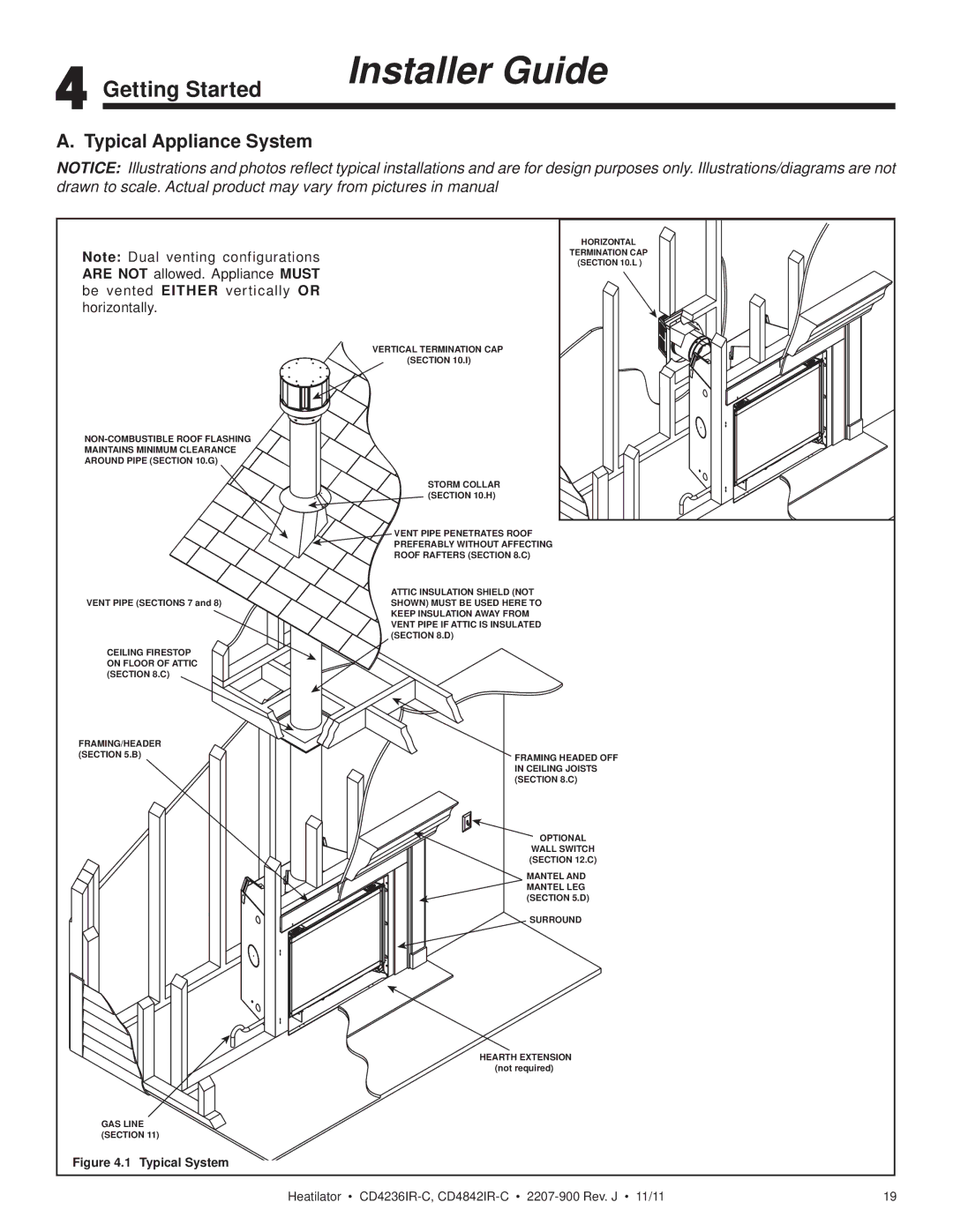
NOTICE: Illustrations and photos reflect typical installations and are for design purposes only. Illustrations/diagrams are not drawn to scale. Actual product may vary from pictures in manual
Note: Dual venting configurations ARE NOT allowed. Appliance MUST be vented EITHER vertically OR horizontally.
![]() MAINTAINS MINIMUM CLEARANCE
MAINTAINS MINIMUM CLEARANCE ![]() AROUND PIPE (SECTION 10.G)
AROUND PIPE (SECTION 10.G) ![]()
VERTICAL TERMINATION CAP (SECTION 10.I)
STORM COLLAR (SECTION 10.H)
HORIZONTAL
TERMINATION CAP (SECTION 10.L )
VENT PIPE (SECTIONS 7 and 8)
CEILING FIRESTOP ON FLOOR OF ATTIC (SECTION 8.C)
FRAMING/HEADER (SECTION 5.B)
GAS LINE (SECTION 11)
Figure 4.1 Typical System
VENT PIPE PENETRATES ROOF
PREFERABLY WITHOUT AFFECTING
ROOF RAFTERS (SECTION 8.C)
ATTIC INSULATION SHIELD (NOT SHOWN) MUST BE USED HERE TO KEEP INSULATION AWAY FROM VENT PIPE IF ATTIC IS INSULATED (SECTION 8.D)
FRAMING HEADED OFF IN CEILING JOISTS (SECTION 8.C)
OPTIONAL
WALL SWITCH (SECTION 12.C)
MANTEL AND MANTEL LEG (SECTION 5.D)
SURROUND
HEARTH EXTENSION (not required)
Heatilator • | 19 |