5 Framing and Clearances
A. Selecting Appliance Location
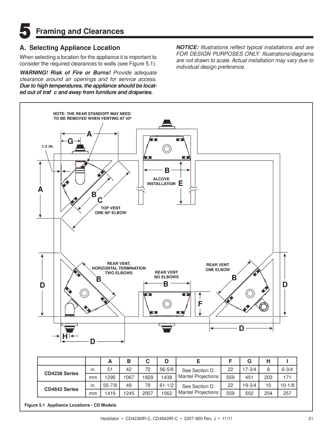
When selecting a location for the appliance it is important to consider the required clearances to walls (see Figure 5.1).
WARNING! Risk of Fire or Burns! Provide adequate clearance around air openings and for service access.
Due to high temperatures, the appliance should be locat- ed out of traffic and away from furniture and draperies.
NOTICE: Illustrations reflect typical installations and are FOR DESIGN PURPOSES ONLY. Illustrations/diagrams are not drawn to scale. Actual installation may vary due to individual design preference.
NOTE: THE REAR STANDOFF MAY NEED
TO BE REMOVED WHEN VENTING AT 45º
A
![]() G
G![]()
![]()
1/2 IN.
| B | |
| ALCOVE | |
A | INSTALLATION E | |
BC | ||
| ||
| TOP VENT | |
| ONE 90º ELBOW |
| REAR VENT, |
| REAR VENT |
| HORIZONTAL TERMINATION |
| |
| REAR VENT | ONE ELBOW | |
| TWO ELBOWS | ||
| B | ||
| B | NO ELBOWS | |
|
|
| |
D |
| B |
|
D
H![]()
![]()
F
D
D
|
|
| A | B | C | D |
| E | F | G | H | I |
| |
| CD4236 Series | in. | 51 | 42 | 72 |
| See Section D. | 22 | 8 |
|
| |||
| mm | 1295 | 1067 | 1829 | 1438 |
| Mantel Projections | 559 | 451 | 203 | 171 |
|
| |
|
|
|
|
| ||||||||||
| CD4842 Series | in. | 49 | 79 |
| See Section D. | 22 | 10 |
|
| ||||
| mm | 1419 | 1245 | 2007 | 1562 |
| Mantel Projections | 559 | 502 | 254 | 257 |
|
| |
|
|
|
|
| ||||||||||
Figure 5.1 Appliance Locations - CD Models |
|
|
|
|
|
|
|
|
|
|
| |||
|
|
|
|
|
|
|
|
|
|
|
|
|
|
|
|
|
| Heatilator | • | • | 11/11 |
|
| 21 | |||||