B. Constructing the Appliance Chase
A chase is a vertical
NOTICE: Treatment of ceiling firestops and wall shield firestops and construction of the chase may vary with the type of building. These instructions are not substitutes for the requirements of local building codes. Therefore, you MUST check local building codes to determine the requirements to these steps.
Chases should be constructed in the manner of all out- side walls of the home to prevent cold air drafting prob- lems. The chase should not break the outside building envelope in any manner.
Walls, ceiling, base plate and cantilever floor of the chase should be insulated. Vapor and air infiltration barriers should be installed in the chase as per regional codes for the rest of the home. Additionally, in regions where cold air infiltration may be an issue, the inside surfaces may be sheetrocked and taped for maximum air tightness.
To further prevent drafts, the wall shield and ceiling fire- stops should be caulked with caulk with a minimum of 300ºF continuous exposure rating to seal gaps. Gas line holes and other openings should be caulked with caulk with a minimum of 300ºF continuous exposure rating or stuffed with unfaced insulation. If the appliance is being installed on a cement surface, a layer of plywood may be placed underneath to prevent conducting cold up into the room.
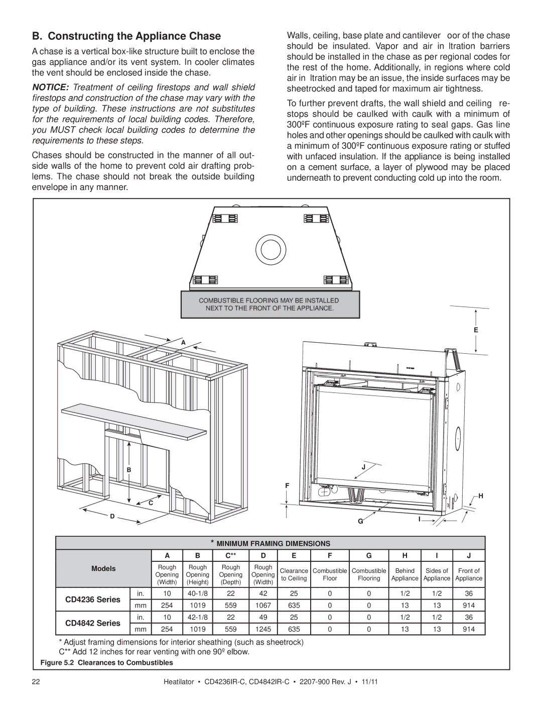
COMBUSTIBLE FLOORING MAY BE INSTALLED
NEXT TO THE FRONT OF THE APPLIANCE.
E
A
BJ
F
H
C
![]() D
D
G![]() I
I
*MINIMUM FRAMING DIMENSIONS
|
| A | B | C** | D | E | F | G | H | I | J | |
Models |
| Rough | Rough | Rough | Rough | Clearance | Combustible | Combustible | Behind | Sides of | Front of | |
|
| Opening | Opening | Opening | Opening | to Ceiling | Floor | Flooring | Appliance | Appliance | Appliance | |
|
| (Width) | (Height) | (Depth) | (Width) |
|
|
|
|
|
| |
CD4236 Series | in. | 10 | 22 | 42 | 25 | 0 | 0 | 1/2 | 1/2 | 36 | ||
mm | 254 | 1019 | 559 | 1067 | 635 | 0 | 0 | 13 | 13 | 914 | ||
| ||||||||||||
CD4842 Series | in. | 10 | 22 | 49 | 25 | 0 | 0 | 1/2 | 1/2 | 36 | ||
mm | 254 | 1019 | 559 | 1245 | 635 | 0 | 0 | 13 | 13 | 914 | ||
|
*Adjust framing dimensions for interior sheathing (such as sheetrock) C** Add 12 inches for rear venting with one 90º elbow.
Figure 5.2 Clearances to Combustibles
22 | Heatilator • |