520 specifications
Henny Penny 520 is a professional frying equipment that caters to the needs of both small food establishments and large-scale commercial kitchens. This innovative fryer combines efficiency and technology to deliver consistent and high-quality results in frying, making it a popular choice among restaurant owners and chefs.One of the main features of the Henny Penny 520 is its advanced cooking system that utilizes a patented pressure frying technology. This method not only shortens cooking times but also enhances the flavor and moisture retention of the food, resulting in a juicy and perfectly cooked product. The increased pressure allows for even heat distribution, ensuring that every piece is cooked uniformly.
The temperature control system in the Henny Penny 520 is highly sophisticated, allowing for precise adjustments to meet the specific requirements of different foods. The fryer can heat up quickly and maintain consistent temperature levels during the frying process, reducing the chances of overcooking or undercooking. The digital control panel provides an intuitive interface for users, making it easy to set cooking times and temperatures with accuracy.
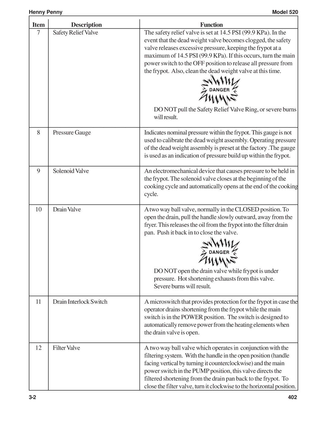
Another significant characteristic of the Henny Penny 520 is its energy efficiency. The fryer is designed to minimize oil usage while still delivering excellent frying results. This not only helps reduce operating costs but also contributes to a more environmentally friendly kitchen operation. Additionally, the fryer features a built-in filtration system that helps extend the life of the oil, ensuring that food tastes fresh and reducing the frequency of oil replacement.
The construction of the Henny Penny 520 is robust and durable, designed to withstand the rigors of daily use in a busy kitchen. The stainless steel body not only adds to the aesthetics but also contributes to its longevity and ease of cleaning. Safety features are also incorporated into the design, with automatic shut-off mechanisms and temperature sensors to prevent overheating and potential hazards.
In summary, the Henny Penny 520 is a versatile and efficient frying solution that stands out due to its advanced pressure frying technology, precise temperature control, energy efficiency, and durable construction. Its ability to produce high-quality, flavorful fried foods consistently makes it a valuable asset to any culinary establishment, meeting the demands of both chefs and patrons alike.

