Trademark acknowledgment
Thank you for purchasing this projector
Basic operation
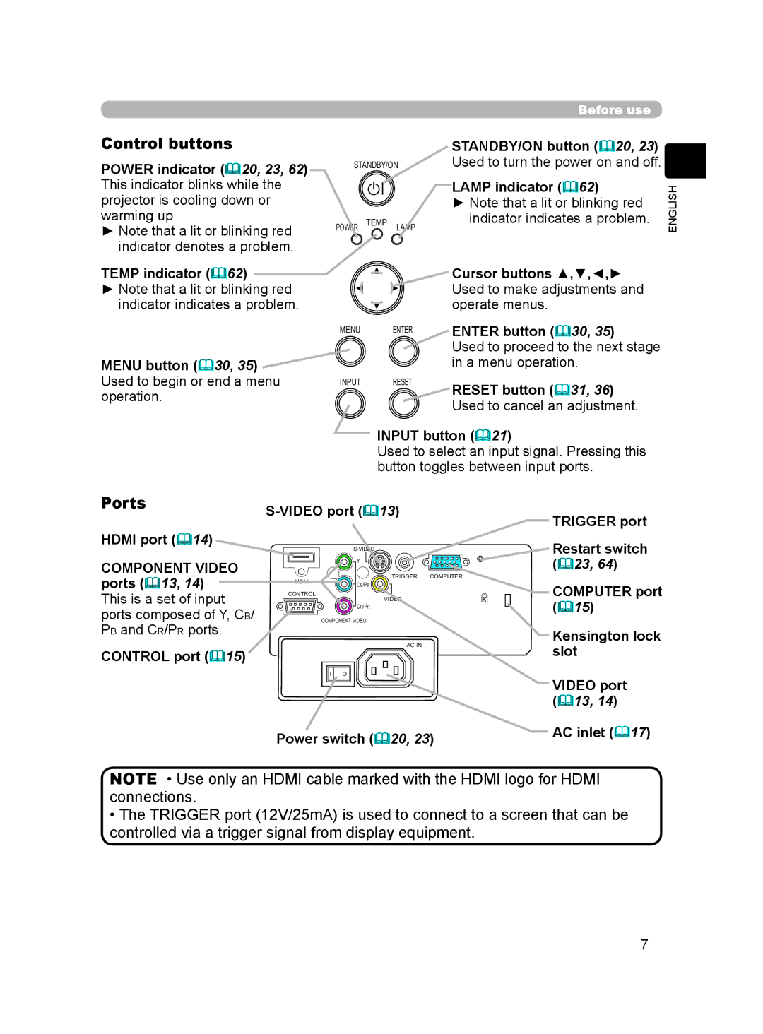
Before use
Preparations
Projection
Advanced Menu
Maintenance
Troubleshooting
Warranty and after-service Specifications
About this manual
Projector features
About contents of package
Projector
Part names
Ports
Control buttons
Component Video
CONTRAST, Bright
Remote control
PC, HDMI, Compo
Strap
Fastening the lens cover
Strap hole Rivet
On a horizontal surface Suspended from the ceiling
Arrangement
For 43 screens
For 169 screens
Adjusting the projector’s elevation
With a VCR/DVD player
Connecting your devices
For a DVI signal source
For an Hdmi signal source
For an Scart RGB input
Optional Use
With a computer
Vesa
Computer signal examples
About Plug-and-Play capability
Vesa Text
Using the cable cover
Connecting the power supply
Loading batteries into the remote control
Light button
Using the remote control
Using the remote control button lights
Remote control Sensor Approximately
STANDBY/ON button
Turning the power on
Power button
Power indicator
Automatically adjusting the picture
Selecting an input signal
Zoom ring
Adjusting the display position
Adjusting the zoom
Adjusting the focus
Turning the power off
MOVIE1 MOVIE2
For no signal or an unrecognized signal 169 fixed
169
Wide
Dark
Bright
Cinema LOW
Mode Gamma Color Iris
Temp
Normal Standard
AUTO2
Bright Dark
Turn OFF
AUTO1
MY Memory
To load saved adjustment settings
MY MEMORY
To save adjustment settings
To change the display language
To display a menu when no menu is currently displayed
To switch from the Advanced Menu to the Easy Menu
Easy Menu operation
To close the menu
To reset the operation
Easy Menu functions
To operate the selected item
Music
Normal
Cinema LOW
Cinema High
Mirror
Darker Brighter
Weaker Stronger
Reddish Greenish
Language Svenska Русский Suomi Polski Türkçe
Reset
English Français Deutsch Español
Italiano Norsk Nederlands Português
Advanced Menu operation
To switch from the Easy Menu to the Advanced Menu
To select a menu
To reset the menu settings
CUSTOM-1, CUSTOM-2, CUSTOM-3, CUSTOM-4
Picture menu
Standard
High
Step Ramp Gray scale
Description To adjust a Custom mode
6500K, 7500K, 9300K
These modes set the same color temperature as the mode name
6500K 7500K 9300K Hi-BRIGHT
CUSTOM-1 CUSTOM-2 CUSTOM-3 CUSTOM-4
Greenish Reddish
Step Ramp Gray scale
Iris
Memory
Description To save adjustment settings
Image menu
Using the / cursors buttons changes the aspect ratio
Over Scan
For a signal from the S-VIDEO or Video port
For a signal from the Computer port
For a signal from the Hdmi port
For a signal from the Component Video ports
Auto
Input menu
TV Film Turn OFF
Film
NTSC, PAL, SECAM, NTSC4.43, M-PAL, N-PAL
Component Scart RGB
Component
Scart RGB
Example for a Scart RGB signal
Example for computer RGB signals
Example for an Hdmi signal
Example for a video, s-video and component video signal
Normal Whisper
Setup menu
Reduce top of the image Reduce bottom of the image
Keystone
Language
Screen menu
Menu Position
Original
MyScreen Original Turn OFF
MyScreen
Start UP
Message
To move the black bars up and down
Using the / cursor buttons switches between the dialogs
Option menu
Reset Cancel
Long max min. Short min min
Ghost
FAN Speed Ghost Stripe Factory Reset Filter Message
Using the / cursor buttons changes the rotation
High Normal
Filter Message
Factory Reset
50h 100h 200h 300h Turn OFF
Lamp
Bottom Projector Lamp cover Screw
Replacing the lamp by yourself
Filter
Air filter
Air filter Knobs
Maintenance
Inside of the projector
Cabinet and Remote control
Lens
Related messages
There is no input signal
Horizontal or vertical wavelength of the input signal
Internal temperature is high
Power Lamp Temp
Regarding the indicator lamps
Has overheated
Indicator Cooling fan is not operating
It is time to clean the air filter
There is a possibility that the interior of the projector
Lens cover is closed
Main power source has been interrupted during operation
By a power outage blackout, etc
Signal cables are not correctly connected
Color Space setting is not suitable
Brightness is adjusted to an extremely low level
Menu function or the remote control
Color settings are not correctly adjusted
Fan speed has been automatically changed
Set the Whisper item 48 in the Setup menu to Normal
Whisper function is working
Whisper function may cause screen flicker
Communication port
Specification
RGB input port
Digital input port
Unit mm
Dimension diagram
Ntsc
Entry Explanation
Interface which is an interface standard for
40, 43, 44
Scart
PAL
Secam