CHAPTER 2 MOUNTING METHOD OF OPTION
2.1 Mounting method of option
Please connect the following cables first, and then attach the
(1)mounting location
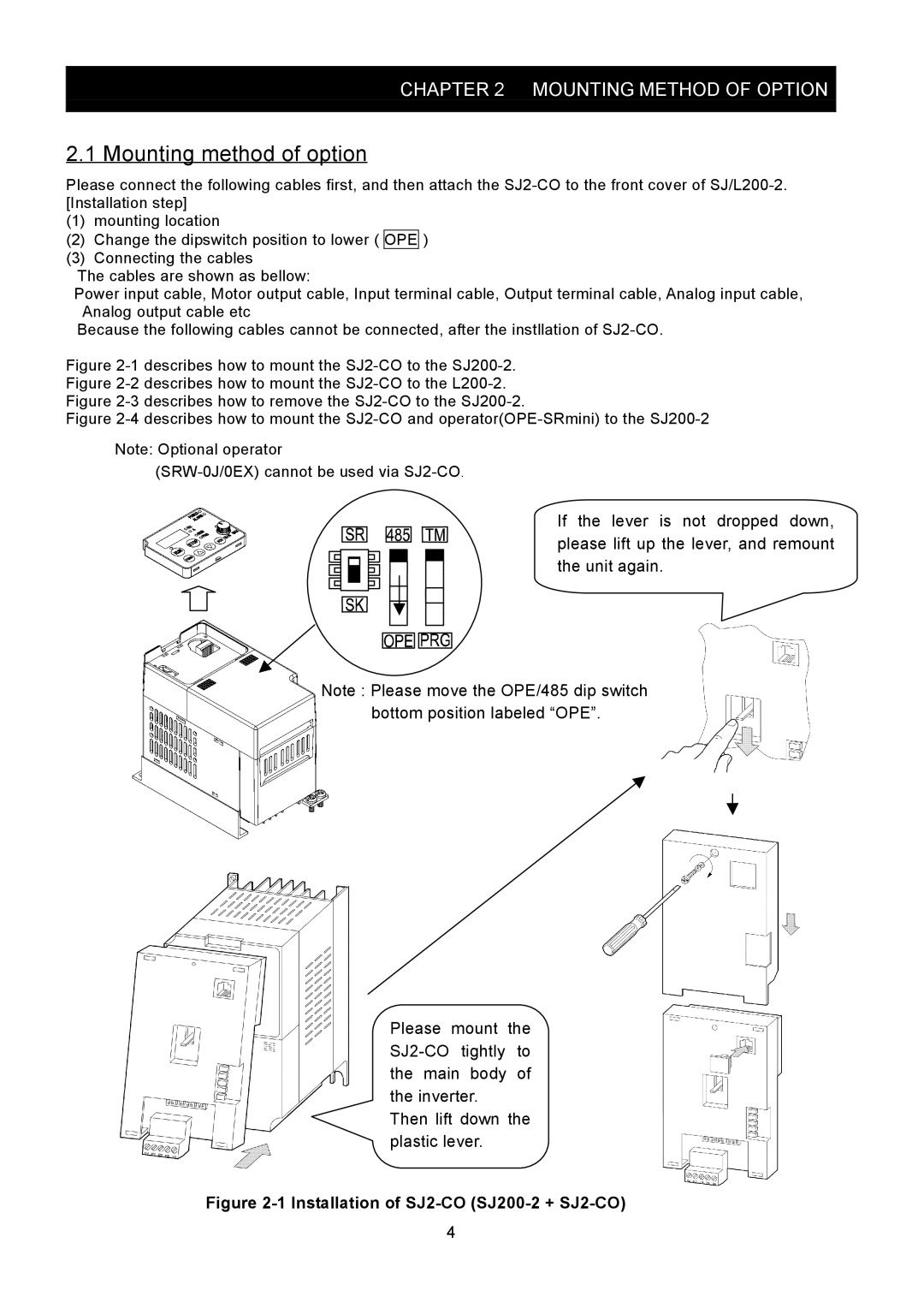
(2)Change the dipswitch position to lower ( OPE )
(3)Connecting the cables
The cables are shown as bellow:
Power input cable, Motor output cable, Input terminal cable, Output terminal cable, Analog input cable, Analog output cable etc
Because the following cables cannot be connected, after the instllation of
Figure 2-1 describes how to mount the SJ2-CO to the SJ200-2. Figure 2-2 describes how to mount the SJ2-CO to the L200-2. Figure 2-3 describes how to remove the SJ2-CO to the SJ200-2.
Figure 2-4 describes how to mount the SJ2-CO and operator(OPE-SRmini) to the SJ200-2
Note: Optional operator
(SRW-0J/0EX) cannot be used via SJ2-CO.
If the lever is not dropped down, please lift up the lever, and remount the unit again.
Note : Please move the OPE/485 dip switch bottom position labeled “OPE”.
Please mount the
Then lift down the plastic lever.
Figure 2-1 Installation of SJ2-CO (SJ200-2 + SJ2-CO)
4
