223 112C
2006−08
Flux Cored (FCAW) Welding
Arc Welding Power Source And
Wire Feeder
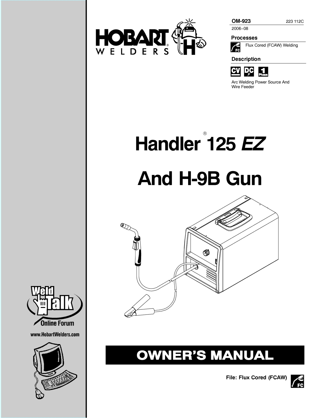
HandlerR125 EZ
And H-9B Gun