Manuals
/
Hobart Welding Products
/
Power Tools
/
Welder
Hobart Welding Products
OM-230 455D
manual
Models:
OM-230 455D
1
34
36
36
Download
36 pages
19.36 Kb
29
30
31
32
33
34
35
36
Troubleshooting
Specs
Parts list
Electrical Diagram
Symbol Usage
Connecting Work Clamp
Dimension
Maintenance
How to
Safety
Page 34
Image 34
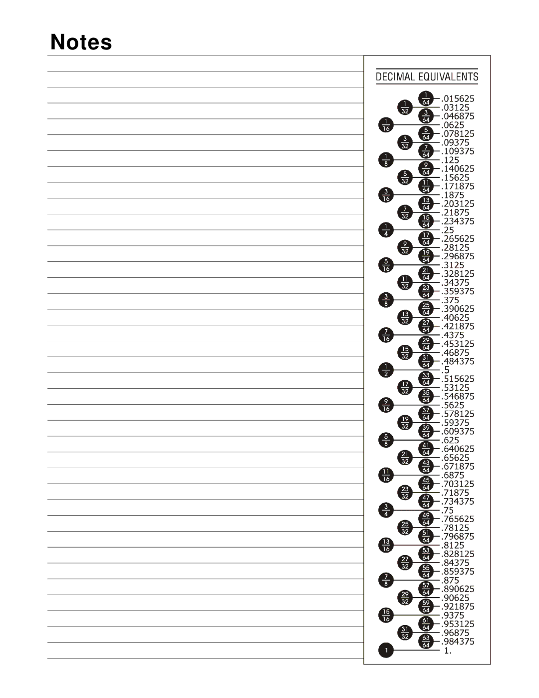
Notes
Page 33
Page 35
Page 34
Image 34
Page 33
Page 35
Contents
Description
OM-230 455D
Processes
File Plasma Cutters
From Hobart to You
Protect Your Investment
Table of Contents
Page
Plasma Arc Cutting Hazards
Symbol Usage
Marks a special safety message
Cutting can cause fire or explosion
ARC Rays can burn eyes and skin
Exploding Parts can injure
Flying Sparks can cause injury
Noise can damage hearing
California Proposition 65 Warnings
EMF Information
Principal Safety Standards
About Pacemakers
UNE Décharge Électrique peut entraîner la mort
Signification des symboles
LE Coupage présente un risque de feu ou d’explosion
Identifie un message de sécurité particulier
LES Fumées ET LES GAZ peuvent être dangereux
Risque de blessure en cas
LE Bruit peut endommager l’ouïe
LE Plasma D’ARC peut entraîner des blessures
LA Chute DE L’APPAREIL peut blesser
DES Pieces Chaudes peuvent pro- voquer des brûlures graves
DES Organes Mobiles peuvent provoquer des blessures
Risque D’INCENDIE OU
LE Coupage à L’ARC peut causer des interférence
Principales normes de sécurité
Information sur les champs électromagnétiques
Consignes relatives aux stimulateurs cardiaques
I1max
− Definitions
I1eff
Specifications For Torch
− Installation
Specifications For Power Source
Duty Cycle And Overheating
Selecting a Location
Torch Dimensions And Weight
Dimensions And Weight
Movement, Location And Airflow
Electrical Service Guide For 120 VAC
Connecting Work Clamp
Extension Cord Data
Check input voltage available at site Grounded Receptacle
Connecting Input Power
Generator Or Inverter Requirements
Plug From Unit
Cable Management Strap
Electrode Wrench
Controls
− Operation
Recommended Cutting Speed For Material Thickness
Plasma Cutting System Practices
Maintain approximately a 90 angle to
Pilot arc starts immediately
When trigger is pressed
Sequence Of Cutting Operation
Example Of Cutting Operation
Example Of Cutting Using Stand-off Guide
Sequence Of Cutting Using Stand-off Guide
Split section to bottom 16 in 1.6 mm
Sequence Of Piercing Operation
− Maintenance & Troubleshooting
Routine Maintenance
Trouble Lights And Checking Shield Cup Shutdown System
Checking Torch Shield Cup Shutdown System
Checking/Replacing Retaining Cup, Tip, And Electrode
Turn Off power source before checking torch parts
Electrode Wrench
Compressor Filter Cleaning And Replacement
Disconnect input power
Torch Connections
Torch And Work Cable Connections
Work Cable Connections
Only by authorized Service Station
Troubleshooting Power Source
Check Control board PC1
Troubleshooting Torch
− Electrical Diagram
Circuit Diagram
Recommended Spare Parts
− Parts List
Recommended Spare Parts
Material Thickness Gauge
Page
Support
Service
Assistance
Contact your Distributor for
Hobart Welding Products
Top
Page
Image
Contents