Manuals
/
Honeywell
/
Personal Care
/
Blood Pressure Monitor
Honeywell
40002083 installation and operation guide Airport Systems
Models:
40002083
1
34
51
51
Download
51 pages
51.53 Kb
31
32
33
34
35
36
37
38
<
>
Specs
Install
Replacement Parts
Maintenance
HMS Light Configuration Menu
Safety Precautions
Safety
Power Up and System Tests
Day Mode
Page 34
Image 34
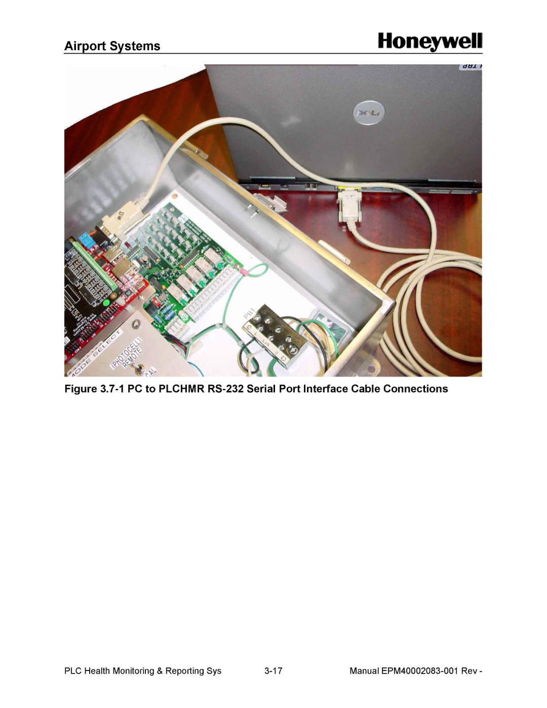
Airport Systems
Figure
3.7-1
PC to PLCHMR
RS-232
Serial Port Interface Cable Connections
PLC Health Monitoring & Reporting Sys
3-17
Manual
EPM40002083-001
Rev -
Page 33
Page 35
Page 34
Image 34
Page 33
Page 35
Contents
Manual Number EPM40002083-001
State Route Urbana, OH Phone 937 Fax 937
ECO#
History of Revisions
Rev Comment
Approved Date Preliminary
Disclaimers
Installation & Power UP
Table of Contents
Safety Information General Information
Maintenance
Table of Figures
1 Plchmr Module
Safety Information
Safety and Workmanship Alerts
Qualified Personnel
Interlocks
Airport Systems
Scope
General Description
Airport Systems
1 Plchmr Module
2 Master Controller with Plchmr Module Installed
3 Model SGF-60E Flash Head
Safety Precautions
Airport Systems
Airport Systems
Specifications
User Supplied Tools
DAY
Installation
Step
Replace existing MCU PN- 40000328 with new MCU PN
Plchmr Module Power Supply Connections
2 Plchmr Module Mounted on and Wired to Master Controller
3 Terminal Block- 8 +16V Red and GND -Black Wire Connections
4 StrobeGuard Control & Status Network Wiring Connections
Step
40000324-001
Flash Head Status Reporting Relay Installation Wiring
1 PLCHMRs Output Relay connection Diagram
Final Installation Check
Power Up and System Tests
Airport Systems
1 Master Controller Circuit Board
Plchmr System Maintenance and Configuration Menus
Airport Systems
2 HMS Maintenance Menu Hierarchy
3 HMS Maintenance Menu
4 HMS Light Configuration Menu
5 HMS Modify Light Menu
6 HMS Report Confguration Menu
Day Mode
Airport Systems
Airport Systems
Overall Description
Plchmr Module
Replacement Parts
Description Part Number
Light Configuration Examples
1 Tower Example with 9 Flash Heads on Three Physical Tiers
Airport Systems
TRM #2 TRM #3 TRM #4 TRM #5 TRM #6
TRM
TRM #7
Airport Systems
5 System Configuration with 24 Flash Heads using 8 relays