INTRODUCTION | A S S E M B LY STEP 6 | |
| ||
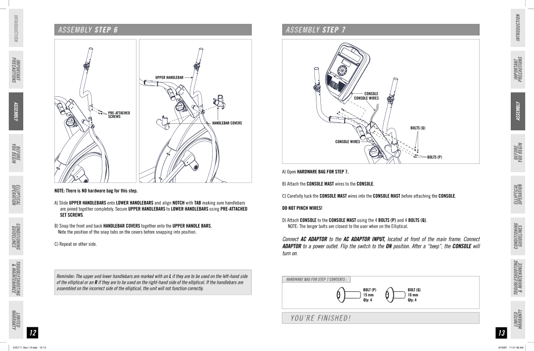
IMPORTANT | UPPER HANDLEBAR | |
PRECAUTIONS |
| |
ASSEMBLY | ||
SCREWS | ||
HANDLEBAR COVERS | ||
| ||
YOU |
| |
BEFORE |
| |
BEGIN |
| |
ELLIPTICAL OPERATION | A) Slide UPPER HANDLEBARS onto LOWER HANDLEBARS and align NOTCH with TAB making sure handlebars | |
| NOTE: There is NO hardware bag for this step. | |
| are joined together completely. Secure UPPER HANDLEBARS to LOWER HANDLEBARS using | |
| SET SCREWS. | |
CONDITIONING | B) Snap the front and back HANDLEBAR COVERS together onto the UPPER HANDLE BARS. | |
C) Repeat on other side. | ||
GUIDELINES | ||
| Note the position of the snap tabs on the covers before snapping into position. | |
TROUBLESHOOTING |
| |
& |
| |
MAINTENANCE | Reminder: The upper and lower handlebars are marked with an L if they are to be used on the | |
| of the elliptical or an R if they are to be used on the | |
| assembled on the incorrect side of the elliptical, the unit will not function correctly. | |
WARRANTY |
| |
LIMITED |
| |
| 12 |
A S S E M B LY STEP 7 |
CONSOLE |
CONSOLE WIRES |
BOLTS (Q) |
CONSOLE WIRES |
BOLTS (P) |
A)Open HARDWARE BAG FOR STEP 7.
B)Attach the CONSOLE MAST wires to the CONSOLE.
C)Carefully tuck the CONSOLE MAST wires into the CONSOLE MAST before attaching the CONSOLE.
DO NOT PINCH WIRES!
D)Attach CONSOLE to the CONSOLE MAST using the 4 BOLTS (P) and 4 BOLTS (Q). NOTE: The longer bolts are closest to the user when on the Elliptical.
Connect AC ADAPTOR to the AC ADAPTOR INPUT, located at front of the main frame. Connect ADAPTOR to a power outlet. Flip the switch to the ON position. After a “beep”, the CONSOLE will turn on.
HARDWARE BAG FOR STEP 7 CONTENTS :
BOLT (P) | BOLT (Q) |
15 mm | 10 mm |
Qty: 4 | Qty: 4 |
YOU’RE FINISHED!
13
IMPORTANT PRECAUTIONS INTRODUCTION
ASSEMBLY
BEFORE YOU BEGIN
ELLIPTICAL OPERATION
LIMITED TROUBLESHOOTING CONDITIONING WARRANTY & MAINTENANCE GUIDELINES
SXE7.7_Rev.1.6.indd | 8/16/07 11:01:48 AM |