INTRODUCTION IMPORTANT PRECAUTIONS
ASSEMBLY STEP 4
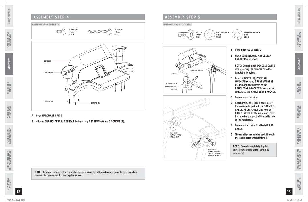
HARDWARE BAG 4 CONTENTS: |
|
SCREW (O) | SCREW (P) |
15 mm | 30 mm |
Qty: 4 | Qty: 2 |
ASSEMBLY STEP 5
HARDWARE BAG 5 CONTENTS:
BOLT (K) | FLAT WASHER (B) | SPRING WASHER (C) |
20 mm | 8 mm | 8 mm |
Qty: 4 | Qty: 4 | Qty: 4 |
IMPORTANT PRECAUTIONS INTRODUCTION
ASSEMBLY
BEFORE
YOU BEGIN
TREADMILL CONDITIONING TROUBLESHOOTING LIMITED
OPERATION GUIDELINES & MAINTENANCE WARRANTY
12
CONSOLE |
CUP HOLDER |
SCREW (P) |
SCREWS (O) |
AOpen HARDWARE BAG 4.
BAttache CUP HOLDERS to CONSOLE by inserting 4 SCREWS (O) and 2 SCREWS (P).
Note: Assembly of cup holders may be easier if console is flipped upside down before inserting screws. Be careful not to overtighten screws.
HANDLEBAR BRACKET |
CONSOLE |
FLAT WASHERS (B) |
SPRING WASHERS (C) |
BOLTS (K) |
LEFT SIDE: |
CONNECT PULSE |
CABLES ONLY |
RIGHT SIDE: |
CONNECT CONSOLE |
CABLES, PULSE CABLES |
AND POWER CABLES |
AOpen HARDWARE BAG 5.
BPlace CONSOLE onto HANDLEBAR BRACKETS as shown.
Note: Do not pinch CONSOLE CABLE when placing the console onto the handlebar brackets.
CInsert 2 Bolts (K), 2 SPRING WASHERS (C) and 2 FLAT washers
(B) through the bottom of the HANDLEBAR BRACKET to secure the console to the HANDLEBAR BRACKET.
DRepeat on other side.
EReach inside the right underside of the console to pull out the console cable, pulse cable and power cable. Attach to the matching cables that are hanging out of the cable hole in the handlebar.
FRepeat on left side to attach pulse cable.
GThread attached cables back through the cable holes when finished.
Note: Do not completely tighten any screws or bolts until step 6 is complete!
13
ASSEMBLY
BEFORE YOU BEGIN
LIMITED TROUBLESHOOTING CONDITIONING TREADMILL WARRANTY & MAINTENANCE GUIDELINES OPERATION
T901_Rev.2.0.indd | 9/10/08 11:15:40 AM |