Manuals
/
Hornet Car Security
/
Household Appliance
/
Home Security System
Hornet Car Security
700T
manual
table of zones, rapid resume logic, troubleshooting, Trigger Type
Models:
700T
1
26
28
28
Download
28 pages
63.89 Kb
21
22
23
24
25
26
27
28
Troubleshooting
Install
finding the wires you need
What is
system features learn routine
valet/program switch
Page 26
Image 26
Page 25
Page 27
Page 26
Image 26
Page 25
Page 27
Contents
2001 Directed Electronics, Inc. Vista, CA N700T Rev. E
Installation Guide
Model 700T
System Features Learn Routine
table of contents
Auxiliary Harness H2 Wire Connection Guide
Wiring Quick Reference Guide
what is included
installation points to remember
tools required
deciding on component locations
valet/program switch
control module
status LED
optional starter kill relay
obtaining constant
finding the wires you need
finding the 12V switched ignition wire
finding a + parking light wire
finding the door pinswitch circuit
finding the starter wire
making your connections
solderless butt connections
solder connections
H1/1
primary harness H1 wire connection guide
IMPORTANT! Never interrupt any wire other than the starter wire
H1/2
H1/2 WHITE light flash output
H1/3 WHITE/BLUE + trunk release/sensor shunt input
Connect this wire to the optional domelight supervision relay
H1/9 YELLOW + ignition input
H1/7 VIOLET + door trigger input
H1/8 BLACK - chassis ground connection
the same point you connect the control module’s black ground wire
H2/2 GREEN arm input
auxiliary harness H2 wire connection guide
H2/1 BROWN - horn honk output
H2/3 RED disarm defeat input
Passenger Unlock
Lock
Driver’s Unlock
connecting door lock inputs in vehicles with driver’s door unlock and external relays
door lock learn routine
plug-in harnesses
on-board stinger doubleguard shock sensor
internal programming jumper
light flash jumper
system features learn routine
system features menu
TWO CHIRPS - PRESS
8 NO FUNCTION
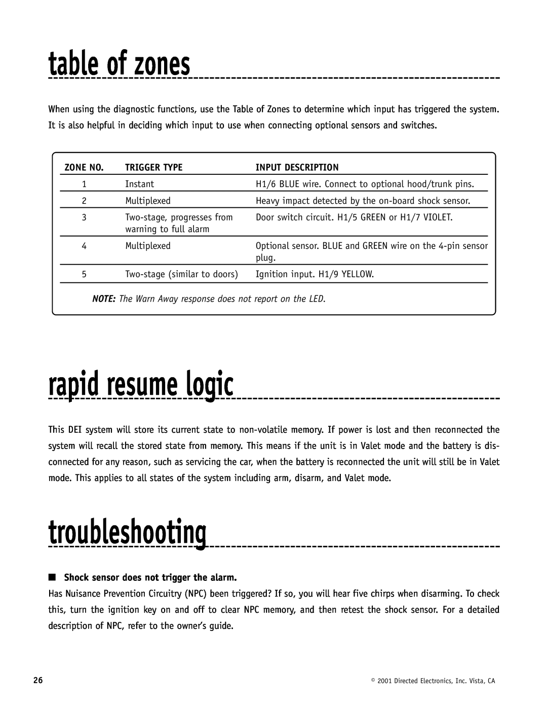
rapid resume logic
troubleshooting
table of zones
Shock sensor does not trigger the alarm
Status LED does not work
The Valet/program switch does not work
Closing the door triggers the system, but opening the door does not
wiring quick reference guide
Top
Page
Image
Contents