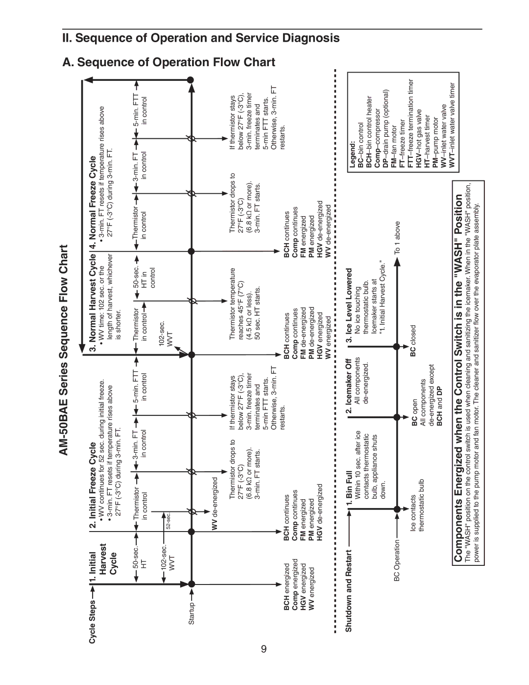
Hoshizaki AM-50BAE Diagnosis, A. Sequence of Operation Flow Chart, Initial Freeze Cycle

Models: AM-50BAE-DS AM-50BAE-ADDS AM-50BAE AM-50BAE-AD

1 38
Download 38 pages 29.09 Kb
Page 9
Image 9
AM-50BAE Series Sequence Flow Chart

AM-50BAE Series Sequence Flow Chart


Cycle Steps


1. Initial


2. Initial Freeze Cycle


3. Normal Harvest Cycle


4. Normal Freeze Cycle


Harvest


• WV continues for 52 sec. during initial freeze.


• WV time: 102 sec. or the


3-min. FT resets if temperature rises above


Cycle


3-min. FT resets if temperature rises above


length of harvest, whichever


27°F (-3°C) during 3-min. FT.


27°F (-3°C) during 3-min. FT.


is shorter.


50-sec.


Thermistor


3-min. FT


5-min. FTT


Thermistor


50-sec.


Thermistor


3-min. FT


5-min. FTT


HT


in control


 in control


 in control


in control


HT in


in control


 in control


 in control


102-sec.


102-sec.


control


52-sec.


WVT


WVT


Startup


WV de-energized


Thermistor drops to

If thermistor stays


Thermistor temperature


Thermistor drops to

If thermistor stays


27°F (-3°C)


below 27°F (-3°C),


reaches 45°F (7°C)


27°F (-3°C)


below 27°F (-3°C),


(6.8 kΩ or more).

3-min. freeze timer


(4.5 kΩ or less).


(6.8 kΩ or more).

3-min. freeze timer


3-min. FT starts.

terminates and


50 sec. HT starts.


3-min. FT starts.


terminates and


9


5-min FTT starts.


5-min FTT starts.


Otherwise, 3-min. FT


Otherwise, 3-min. FT


BCH energized

BCH continues


restarts.


BCH continues


BCH continues


restarts.


Comp energized

Comp continues


Comp continues


Comp continues


HGV energized

FM energized


FM de-energized


FM energized


WV energized

PM energized


PM de-energized


PM energized


HGV de-energized


HGV energized


HGV de-energized


WV energized


WV de-energized


A. Sequence of Operation Flow Chart

II. Sequence of Operation and Service


Diagnosis

Shutdown and Restart


1. Bin Full


2. Icemaker Off


3. Ice Level Lowered


Within 10 sec. after ice


All components


No ice touching


contacts thermostatic


de-energized.


thermostatic bulb.


bulb, appliance shuts


Icemaker starts at


down.


"1. Initial Harvest Cycle."

BC Operation


To 1 above


Ice contacts

BC open

BC closed


thermostatic bulb

All components


de‑energized except BCH and DP

Components Energized when the Control Switch is in the "WASH" Position

The "WASH" position on the control switch is used when cleaning and sanitizing the icemaker. When in the "WASH" position, power is supplied to the pump motor and fan motor. The cleaner and sanitizer flow over the evaporator plate assembly.

Legend:

BC–bin control

BCH–bin control heater Comp–compressor DP–drain pump (optional) FM–fan motor FT–freeze timer FTT–freeze termination timer HGV–hot gas valve HT–harvest timer PM–pump motor WV–inlet water valve WVT–inlet water valve timer

Page 9
Image 9
Hoshizaki AM-50BAE Diagnosis, A. Sequence of Operation Flow Chart, II. Sequence of Operation and Service, Initial, Harvest