II.CONSTRUCTION
1. GENERAL
|
|
|
| [17] |
|
| [4] |
| [16] |
| [18] |
[6] | [5] | [3] |
|
|
|
[7] |
| [2] |
|
| [19] |
|
| [1] |
|
|
|
|
|
|
|
| [20] |
|
|
|
|
| [21] |
[8] |
|
|
|
|
|
[9] |
| [15] | [27] |
|
|
[10] |
|
|
|
|
|
[11] |
| [14] |
|
| [22] |
|
|
| [26] |
|
|
| [12] |
|
|
|
|
| [13] |
|
|
|
|
|
|
| [25] | [24] | [23] |
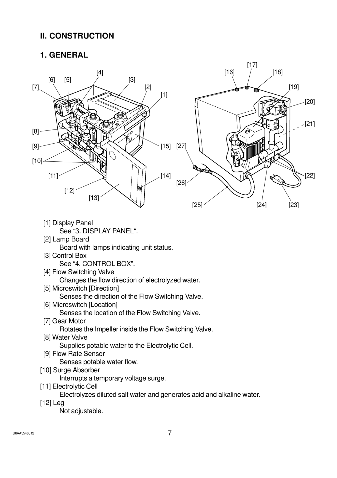
[1] Display Panel
See “3. DISPLAY PANEL“.
[2] Lamp Board
Board with lamps indicating unit status.
[3] Control Box
See “4. CONTROL BOX”.
[4] Flow Switching Valve
Changes the flow direction of electrolyzed water.
[5] Microswitch [Direction]
Senses the direction of the Flow Switching Valve. [6] Microswitch [Location]
Senses the location of the Flow Switching Valve. [7] Gear Motor
Rotates the Impeller inside the Flow Switching Valve. [8] Water Valve
Supplies potable water to the Electrolytic Cell. [9] Flow Rate Sensor
Senses potable water flow. [10] Surge Absorber
Interrupts a temporary voltage surge. [11] Electrolytic Cell
Electrolyzes diluted salt water and generates acid and alkaline water. [12] Leg
Not adjustable.
U8AA5540012 | 7 |
