4. CONTROL BOX
[1]
[2]
[3]
[4]
[13]
[5]
[12]
[6] | [11] |
[10]
[9]
[8]
[7]
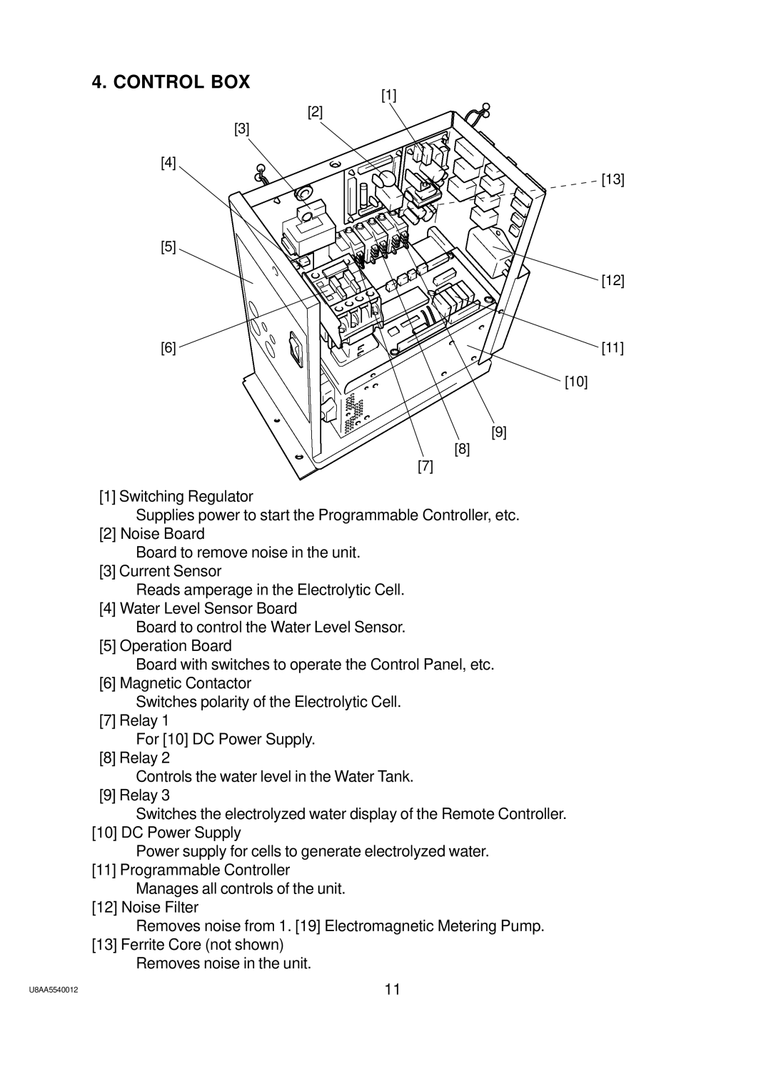
[1] Switching Regulator
Supplies power to start the Programmable Controller, etc.
[2] Noise Board
Board to remove noise in the unit. [3] Current Sensor
Reads amperage in the Electrolytic Cell. [4] Water Level Sensor Board
Board to control the Water Level Sensor. [5] Operation Board
Board with switches to operate the Control Panel, etc. [6] Magnetic Contactor
Switches polarity of the Electrolytic Cell. [7] Relay 1
For [10] DC Power Supply.
[8] Relay 2
Controls the water level in the Water Tank. [9] Relay 3
Switches the electrolyzed water display of the Remote Controller. [10] DC Power Supply
Power supply for cells to generate electrolyzed water.
[11]Programmable Controller Manages all controls of the unit.
[12]Noise Filter
Removes noise from 1. [19] Electromagnetic Metering Pump.
[13]Ferrite Core (not shown) Removes noise in the unit.
U8AA5540012 | 11 |