5.If your device has WWAN capability, remove the SIM (see SIM on page 45).
6.Remove the following components:
a.Keyboard (see Keyboard on page 48)
b.Hard drive or
c.Top cover (see Top cover on page 57)
Remove the display assembly:
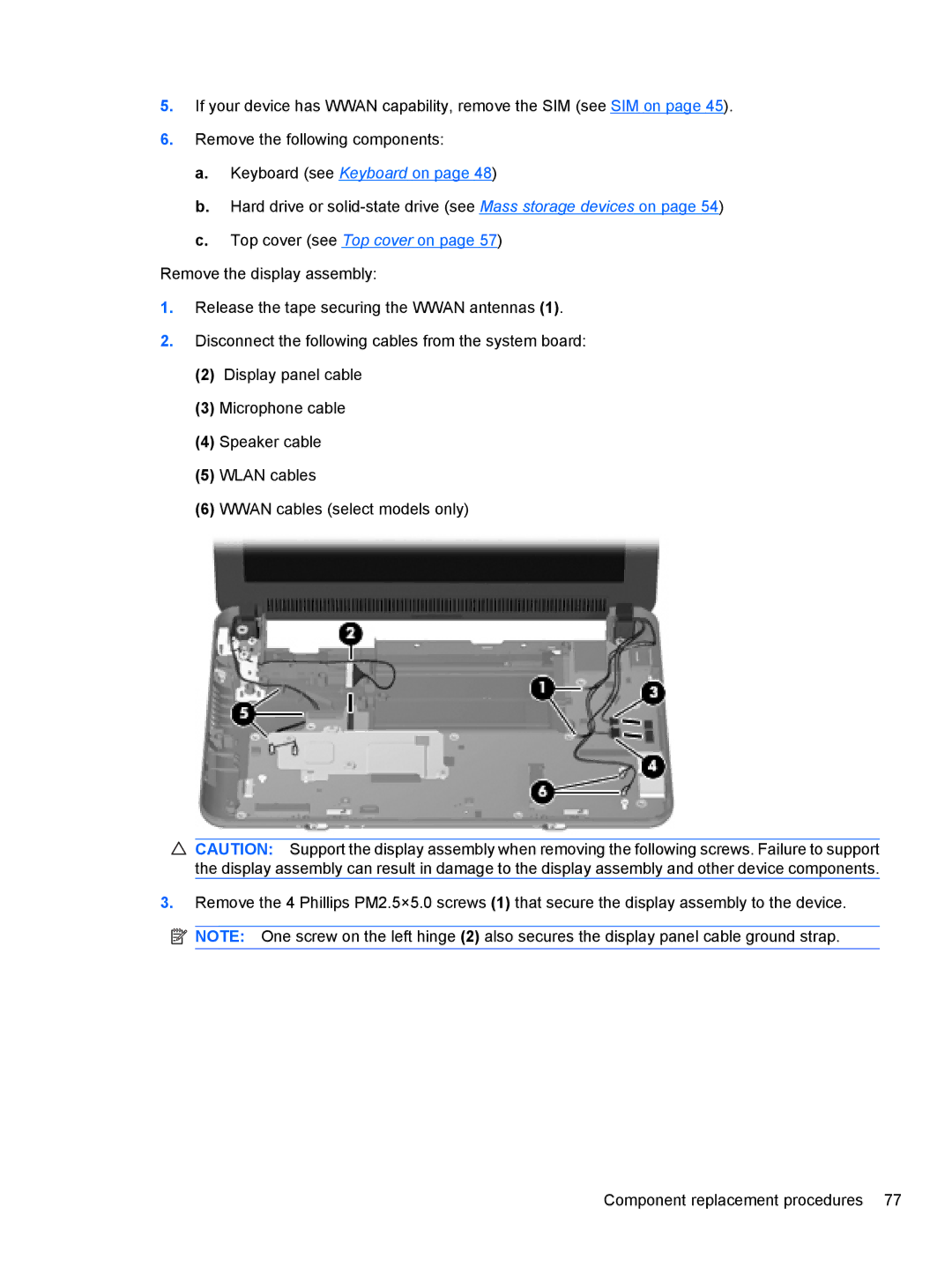
1.Release the tape securing the WWAN antennas (1).
2.Disconnect the following cables from the system board:
(2)Display panel cable
(3)Microphone cable
(4)Speaker cable
(5)WLAN cables
(6)WWAN cables (select models only)
![]() CAUTION: Support the display assembly when removing the following screws. Failure to support the display assembly can result in damage to the display assembly and other device components.
CAUTION: Support the display assembly when removing the following screws. Failure to support the display assembly can result in damage to the display assembly and other device components.
3.Remove the 4 Phillips PM2.5×5.0 screws (1) that secure the display assembly to the device.
![]()
![]()
![]() NOTE: One screw on the left hinge (2) also secures the display panel cable ground strap.
NOTE: One screw on the left hinge (2) also secures the display panel cable ground strap.
Component replacement procedures 77