HP 10Gb Ethernet BL-c Switch
Part number First edition June
Legal notices
Contents
Configuring port-based traffic control
Configuring Lacp
802.1x authentication process
802.1x port states
Adding a Vlan to a Spanning Tree Group Creating a Vlan
Configuration guidelines
Bridge priority Port priority Port path cost
Edge port Link type
106
100
105
109
141
131
Internal versus external routing 134
155
173
Configuring the switch for tracking 177
167
175
Introduction
Accessing the switch
Accessing the switch
Typographical conventions
Typeface or Meaning Example Symbol
Additional references
Management Network
Connecting through Secure Shell
Connecting through the console port
Connecting through Telnet
Using the command line interfaces
Configuring an IP interface
Using the Browser-based Interface
Apply, verify, and save the configuration
For more details, see Configuring Snmp trap hosts
Using Simple Network Management Protocol
Default configuration
Snmp
User configuration
Cfg/sys/ssnmp/snmpv3/usm x/auth md5sha
View based configurations
CLI user equivalent
CLI oper equivalent
Configuring Snmp trap hosts
Configure a user with no authentication or password
SNMPv1 trap host
Accessing the switch Configure an entry in the notify table
Sys/ssnmp/snmpv3/tparam x/uname
SNMPv2 trap host configuration
SNMPv3 trap host configuration
Secure access to the switch
Setting allowable source IP address ranges
How Radius authentication works
Radius authentication and authorization
Configuring an IP address range for the management network
Configuring Radius on the switch CLI example
Apply and save the configuration
Configuring Radius on the switch BBI example
Click Submit
User account
Radius authentication features
User accounts for Radius users
Description and tasks performed
User name/access User service type Value
TACACS+ authentication
Accessing the switch User access levels
Radius attributes for user privileges
Authorization
How TACACS+ authentication works
TACACS+ authentication features
User access level TACACS+ level
Accounting
Configure the TACACS+ secret and second secret
Configure custom privilege-level mapping optional
Configuring TACACS+ authentication on the switch BBI example
Secure Shell and Secure Copy
Configuring SSH and SCP features CLI example
Enabling or disabling SSH
Switch prompts you for the scpadmin password
Using SSH and SCP client commands
Enter the following command to log in to the switch
For example
Generating RSA host and server keys for SSH access
SSH and SCP encryption of management messages
User account Description Password
User access control
SSH/SCP integration with Radius and TACACS+ authentication
Enable the user ID
Setting up user IDs
Define the user name and password
Ports and trunking
Ports on the switch
Ports and trunking
Port number Port alias
Ports and trunking Ethernet switch port names
Before you configure trunks
Built-in fault tolerance
Port trunk groups
Trunk group configuration rules
Cfg/port x/cur
Port trunking example
On Switch 2, configure trunk groups 4
Configuring trunk groups CLI example
On Switch 1, configure trunk groups 5
Configuring trunk groups BBI example
Click Submit
Page
Link Aggregation Control Protocol
Configurable Trunk Hash algorithm
Actor Switch Partner Switch
Page
Apply and verify the configuration
Configuring Lacp
Define the admin key on port
Save your new configuration changes
Extensible authentication protocol over LAN
Port-based Network Access and traffic control
Port-based Network Access control
Port-based Network Access and traffic control
802.1x authentication process
EAPoL Message Exchange
802.1x port states
Supported Radius attributes
Attribute Attribute Value
EAPoL configuration guidelines
Port-based traffic control
Configuring port-based traffic control
VLANs and port Vlan ID numbers
VLANs
Overview
Vlan numbers
Pvid numbers
Viewing and configuring PVIDs
Port configuration
Viewing VLANs
Vlan tagging
VLANs
VLANs
VLANs and IP interfaces
Vlan topologies and design considerations
Vlan configuration rules
Multiple Vlans with tagging
Component Description
VLANs Multiple VLANs with tagging
Configuring the example network
Configuring ports and VLANs on Switch 1 CLI example
# add Add port 18 to Vlan Current Ports for
Configuring ports and VLANs on Switch 2 CLI example
Configuring ports and VLANs on Switch 1 BBI example
VLANs Enable the port and enable Vlan tagging
FDB static entries
Cfg/l2/fdb/static
Configuring a static FDB entry
Trunking support for FDB static entries
Spanning Tree Protocol
Spanning Tree Protocol
Bridge Protocol Data Units
Determining the path for forwarding BPDUs
Spanning Tree Group configuration guidelines
Default Spanning Tree configuration
Rules for Vlan tagged ports
Adding a Vlan to a Spanning Tree Group
Creating a Vlan
Adding and removing ports from STGs
Multiple Spanning Trees
Why do we need Multiple Spanning Trees?
Switch element Belongs to
Assigning cost to ports and trunk groups
Vlan participation in Spanning Tree Groups
Two VLANs on separate instances of Spanning Tree Protocol
Configuring Switch 2 CLI example
Configuring Multiple Spanning Tree Groups
Configuring Switch 1 CLI example
Configuring Switch 1 BBI example
Page
Configuring Fast Uplink Convergence
Configuring Port Fast Forwarding
Configuration guidelines
Port Fast Forwarding
Port state changes
Rstp and Mstp
Rapid Spanning Tree Protocol
Rstp and Mstp
Port type and link type
Rstp configuration guidelines
Rstp configuration example
Configuring Rapid Spanning Tree Protocol BBI example
Mstp region
Rstp and Mstp Apply, verify, and save the configuration
Multiple Spanning Tree Protocol
Common Internal Spanning Tree
Configuring Multiple Spanning Tree Protocol CLI example
Mstp configuration guidelines
Mstp configuration example
Assign VLANs to Spanning Tree Groups
Configuring Multiple Spanning Tree Protocol BBI example
Click Submit
Page
Apply, verify, and save the configuration
Quality of Service
Quality of Service
Number Protocol Name
Using ACL filters
Summary of packet classifiers
Application
Quality of Service Well-known protocol types
Number
Well-krown TCP flag values
Precedence Group ACLs Precedence Level
Summary of ACL actions
Understanding ACL precedence
Using ACL Groups
Metering
ACL Metering and Re-marking
Viewing ACL statistics
Re-marking
ACL configuration examples
Configure Access Control Lists CLI example
Configure Access Control Lists and Groups BBI example
Click Submit
Page
Quality of Service Add the ACL to the port
Per Hop Behavior
Using Dscp values to provide QoS
Differentiated Services concepts
Drop Precedence Class
QoS levels
Using 802.1p priorities to provide QoS
Service Level Default PHB 802.1p Priority
Class selector priority classes
Page
Configure a port’s default 802.1 priority
802.1p configuration CLI example
802.1p configuration BBI example
Quality of Service Select a port 101
Quality of Service Set the 802.1p priority value
102
103
Page
Queuing and scheduling
Routing between IP subnets
Basic IP routing
IP routing benefits
Basic IP routing
Page
Page
Interface Devices IP Interface Address
Example of subnet routing
Subnet Devices IP Addresses
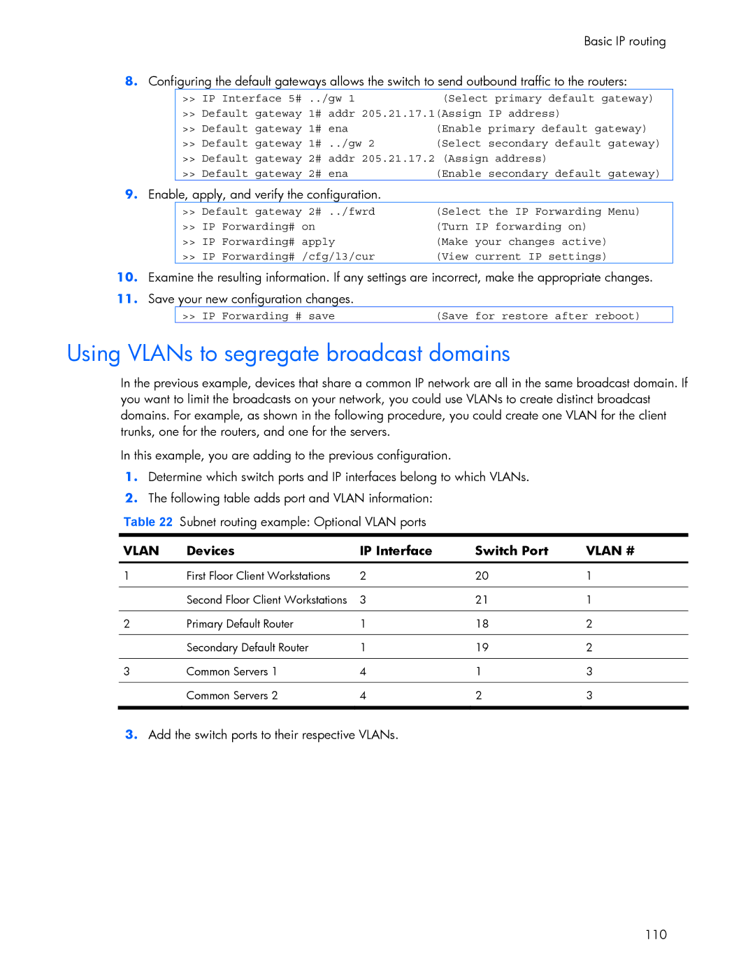
Devices IP Interface Switch Port
Using VLANs to segregate broadcast domains
Enable, apply, and verify the configuration
Add the switch ports to their respective VLANs 110
111
Dynamic Host Configuration Protocol
Dhcp relay agent
Dhcp relay agent configuration
Distance vector protocol
Routing updates
Routing Information Protocol
Stability
RIPv1
RIPv2 in RIPv1 compatibility mode
RIP Features
RIPv2
Multicast
Default
Authentication
Metric
Add IP interfaces to VLANs
RIP configuration example
Add VLANs for routing interfaces
Cfg/l3/frwd/on before you turn RIP on
Igmp Snooping
Igmp Snooping
IGMPv3
FastLeave
Igmp Filtering
Configuring the range
Configuring the action
Enable IGMPv3 Snooping optional
Igmp Snooping configuration example
Configuring Igmp Snooping CLI example
Static multicast router
Enable Igmp Filtering on the switch
Configuring Igmp Filtering CLI example
Configuring a Static Mrouter CLI example
Define an Igmp Filter
Configuring Igmp Snooping BBI example
Igmp Snooping Enable Igmp Snooping
Apply, verify, and save the configuration 124
Configuring Igmp Filtering BBI example
126
Igmp Snooping Define the Igmp Filter
Select Layer 3 Igmp Igmp Filters Add Filter
Page
Apply, verify, and save the configuration 128
Configuring a Static Multicast Router BBI example
Configure Static Mrouter Click the Configure context button
Apply, verify, and save the configuration Igmp Snooping 130
Ospf overview
Types of Ospf areas
Types of Ospf routing devices
Ospf area types
Shortest Path First Tree
Neighbors and adjacencies
Link-State Database
Internal versus external routing
Ospf implementation in HP 10GbE switch software
Configurable parameters
Area index set to an arbitrary value
Defining areas
Assigning the area index
Attaching an area to a network
Using the area ID to assign the Ospf area number
Interface cost
Summarizing routes
Default routes
Electing the designated router and backup
Virtual links
Router ID
Enable Ospf authentication for Area 2 on switch
Enable Ospf MD5 authentication for Area 2 on switch
Configure MD5 key ID for Area 0 on switches 1, 2,
Assign MD5 key ID to Ospf interfaces on switches 1, 2,
Assign MD5 key ID to Ospf virtual link on switches 2
Example 1 Simple Ospf domain CLI example
Ospf configuration examples
Ospf features not supported in this release
Example 1 Simple Ospf domain BBI example
Apply, verify, and save the configuration 143
Ospf
Click Submit
146
Configure the Ospf area
Click Submit Select Add Ospf Area
Ospf
Click Submit Select Add Ospf Interface
148
Apply, verify, and save the configuration 149
Define the backbone
Configuring Ospf for a virtual link on Switch a
Example 2 Virtual links
Switch B in step
Configuring Ospf for a virtual link on Switch B
Configure the virtual link
Attach the network interface to the transit area
Define the transit area
Example 3 Summarizing routes
Other Virtual Link Options
153
Verifying Ospf configuration
Remote monitoring
Remote monitoring
Rmon group 1-statistics
View Rmon statistics for the port
Configuring Rmon Statistics CLI example
Configuring Rmon Statistics BBI example
Remote monitoring Select a port 157
Remote monitoring Enable Rmon on the port
Rmon group 2-history
Configure the Rmon History parameters
History MIB objects
Configure Rmon History BBI example
Apply, verify, and save the configuration 160
Rmon group 3-alarms
Alarm MIB objects
Configure Rmon Alarms BBI example
Configure the Rmon Alarm parameters to track Icmp messages
Apply, verify, and save the configuration 163
164
Configure the Rmon Event parameters
Configuring Rmon Events CLI example
Remote monitoring Apply, verify, and save the configuration
Rmon group 9-events
Configuring Rmon Events BBI example
Apply, verify, and save the configuration 166
High availability
High availability
Uplink Failure Detection
Failure Detection Pair
Spanning Tree Protocol with UFD
Configuring Uplink Failure Detection
Monitoring Uplink Failure Detection
Turn UFD on
Configuring UFD on Switch 1 CLI example
Configuring UFD on Switch 2 CLI example
Create a trunk group of uplink ports 18-21 to monitor
Configuring Uplink Failure Detection BBI example
Apply, verify, and save the configuration 172
Virtual router
Vrrp overview
Vrrp components
Virtual router MAC address
Selecting the master Vrrp router
Master and backup virtual router
Vrrp operation
Virtual Interface Router
Failover methods
Active-Active redundancy
Parameter
HP 10GbE switch extensions to Vrrp
Tracking Vrrp router priority
Assigning Vrrp virtual router ID
Configuring the switch for tracking
Virtual router deployment considerations
Task 1 Configure Switch a
High availability configurations
Active-Active configuration
Configure ports
Turn off Spanning Tree Protocol globally
High availability Configure client and server interfaces
Turn on Vrrp and configure two Virtual Interface Routers
179
Task 2 Configure Switch B
Task 1 Configure Switch a BBI example
Vrrp Virtual Router 1#
Click Submit
183
184
Page
High availability Enable Vrrp processing
Click Submit Select Add Virtual Router
187
Click Submit
High availability 189
Apply, verify, and save the configuration 190
Port Mirroring
Troubleshooting tools
Troubleshooting tools
View the current configuration
Configuring Port Mirroring CLI example
Enable Port Mirroring
Select the ports that you want to mirror
Configuring Port Mirroring BBI example
Click Add Mirrored Port
Other network troubleshooting techniques
Page
197
Index
Index
198