5.Connect the other end of the power cord to the RPS. Figure 65 Connect the RPS cable to the +12 VDC RPS receptacle
Connecting the switch to a –52 to –55 VDC output RPS
This section applies to the
To connect these switches to the RPS that provides
1.Wear an
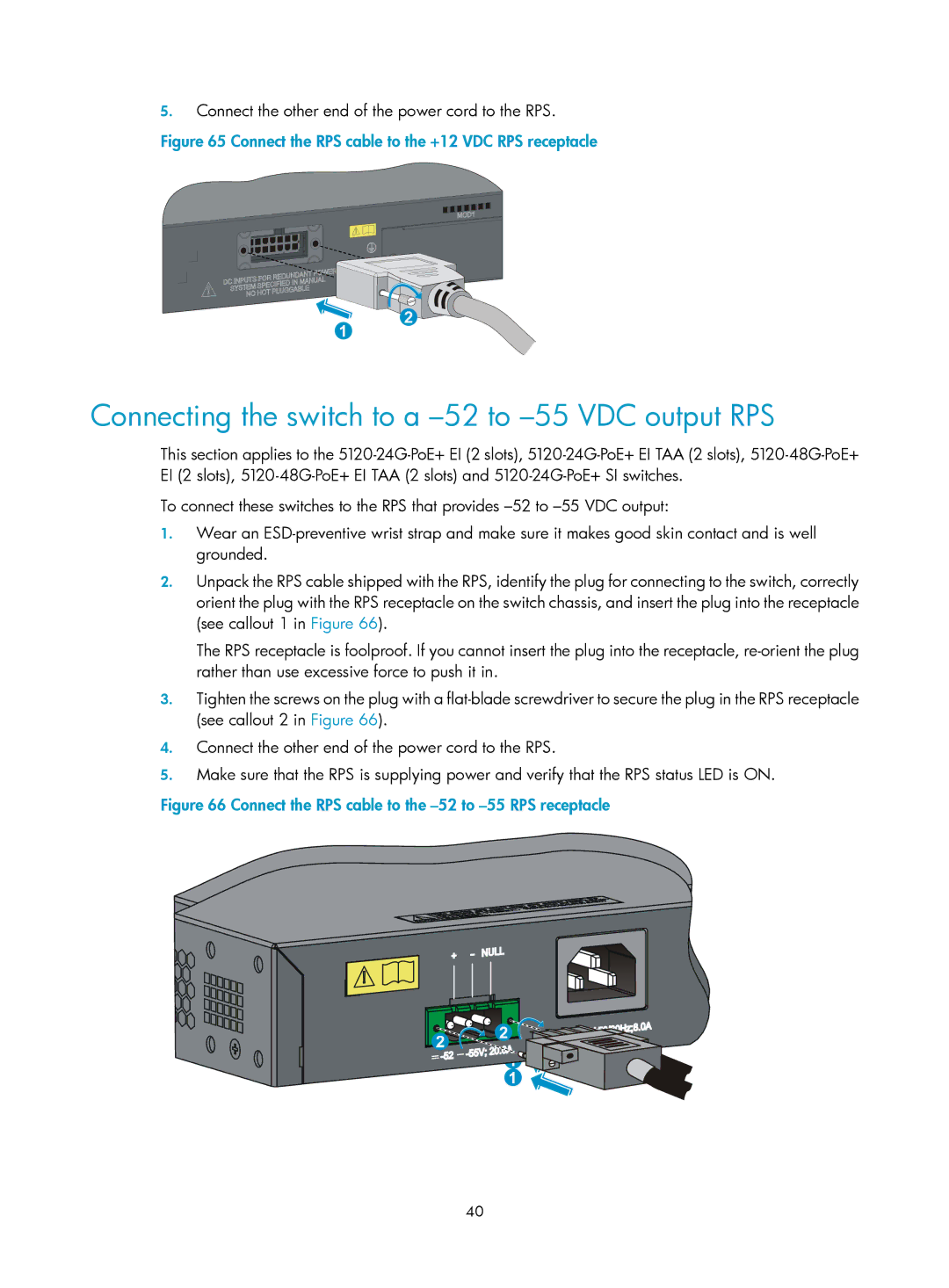
2.Unpack the RPS cable shipped with the RPS, identify the plug for connecting to the switch, correctly orient the plug with the RPS receptacle on the switch chassis, and insert the plug into the receptacle (see callout 1 in Figure 66).
The RPS receptacle is foolproof. If you cannot insert the plug into the receptacle,
3.Tighten the screws on the plug with a
4.Connect the other end of the power cord to the RPS.
5.Make sure that the RPS is supplying power and verify that the RPS status LED is ON.
Figure 66 Connect the RPS cable to the –52 to –55 RPS receptacle
40