Manuals
/
HP
/
Computer Equipment
/
Laptop
HP
CQ56-104CA, CQ56-110US, CQ56-109WM, CQ56-100XX, CQ56-112NR, CQ56-115DX, CQ56-122NR, CQ56-219WM
manual
Models:
CQ56-110US
CQ56-219WM
CQ56-100XX
CQ56-124CA
CQ56-122NR
CQ56-109WM
CQ56-201NR
CQ56-154CA
CQ56-115DX
CQ56-112NR
CQ56-134CA
CQ56-148CA
CQ56-104CA
1
1
2
3
4
5
6
7
8
9
10
11
12
13
14
15
16
17
18
19
20
21
22
23
24
25
26
27
28
29
30
31
32
33
34
35
36
37
38
39
40
41
42
43
44
45
46
47
48
49
50
51
52
53
54
55
56
57
58
59
60
61
62
63
64
65
66
67
68
69
70
71
72
73
74
75
76
77
78
79
80
81
82
83
84
85
86
87
88
89
90
91
92
93
94
95
96
97
98
99
100
101
102
103
104
105
106
107
108
109
110
110
Download
110 pages
8.74 Kb
101
102
103
104
105
106
107
108
109
110
Specifications
Install
Wireless
System Configuration menu
Random access time
Setup Utility
Cables and connectors
Display assembly
Battery
Backup and recovery
Page 107
Image 107
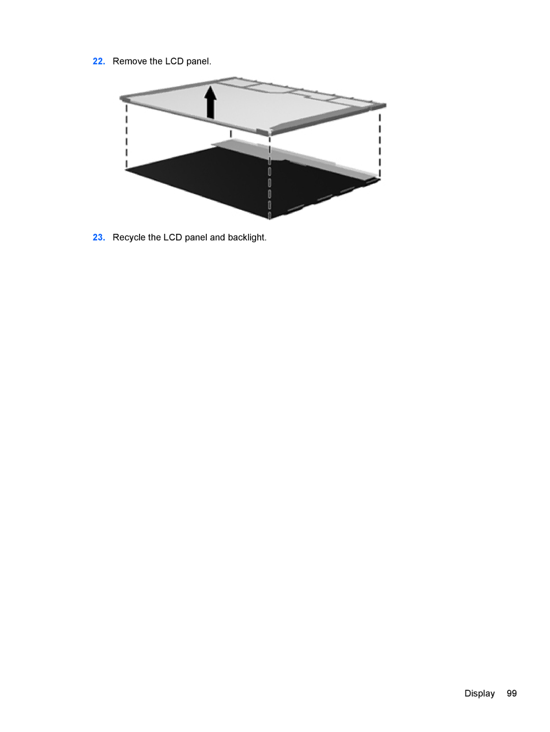
22.
Remove the LCD panel.
23.
Recycle the LCD panel and backlight.
Display 99
Page 106
Page 108
Page 107
Image 107
Page 106
Page 108
Contents
Compaq Presario CQ56 Notebook PC and HP G56 Notebook PC
Page
Safety warning notice
Iv Safety warning notice
Table of contents
Setup Utility
100
Viii
Category Description CQ56
Product description
HP G56
Memory
Chipset
Graphics
Panel
Webcam Select models only. VGA camera
Wireless
Optical
Drives
Keyboard
Power
Operating Preinstalled System
Serviceability End-user replaceable parts
Component Description
External component identification
Top
TouchPad
Lights
Button and speakers
Esc key
Keys
Right side
Left side
Display
Wireless antennas
Bottom
Additional hardware
Illustrated parts catalog
Service tag
Illustrated parts catalog
Computer major components
Display assembly components on
Display assembly
Description Spare part number
Speaker assembly includes cable
Power button board
Power connector includes cable
Plastics Kit
Wireless Wlan module
Battery
Base enclosure
Display panel
Display assembly components
Description Spare part number Display bezel
Display inverter
Display Screw Kit not illustrated
Display hinge covers
Microphone and cable Webcam module select models only
Display back cover includes logo
Item Description Spare part number Plastics Kit 595200-001
Plastics Kit
Hard drive
Mass storage devices
Miscellaneous parts
Spare part number Description
Sequential part number listing
Cable, and webcam cable
Sequential part number listing
AMD
Tools required
Removal and replacement procedures
Preliminary replacement requirements
Service considerations
Cables and connectors
Event 10% 40% 55%
Grounding guidelines
Typical electrostatic voltage levels
Packaging and transporting guidelines
Material Use Voltage protection level
Equipment guidelines
Service tag
Component replacement procedures
Computer feet
Battery
Hard drive
Page
Optical drive
Battery see Battery on Hard drive see Hard drive on
Page
Page
Wlan module
Page
Memory module
Page
Keyboard
Battery see Battery on
Page
Page
Wlan module see Wlan module on Keyboard see Keyboard on
Top cover
Page
Remove the top cover Component replacement procedures
Speaker assembly
Page
Description Spare part number Power button board 595204-001
Power button board
TouchPad button board
Description Spare part number USB board 595205-001
USB board
Page
Power connector
Display assembly
Page
Page
Page
Page
Page
Page
System board
Page
Page
Description Spare part number RTC battery 602745-001
RTC battery
Page
Fan/heat sink assembly
Page
Page
Page
Processor
Page
Using Setup Utility
Setup Utility
Computer Setup
Starting Setup Utility
Navigating and selecting in Setup Utility
Restoring default settings in Setup Utility
Select To do this
Setup Utility menus
Primary Hard Disk Self Test
System Configuration menu
Computer specifications
Specifications
39.6-cm15.6-in display specifications
Hard drive specifications
Cache buffer Data transfer rate
Random access time
Transfer mode
Applicable disc
Backing up your information
Backup and recovery
Windows 7 backup and recovery
Select Start All Programs Maintenance Backup and Restore
Performing a recovery
Using the Windows recovery tools
Using a Windows 7 operating system DVD purchased separately
Linux backup and recovery
Requirements for all countries or regions
Power cord set requirements
Country/region Accredited agency Applicable note number
Requirements for specific countries or regions
Recycling
Battery
Page
Page
Page
Page
Page
Page
Index
Jacks
Top
Page
Image
Contents