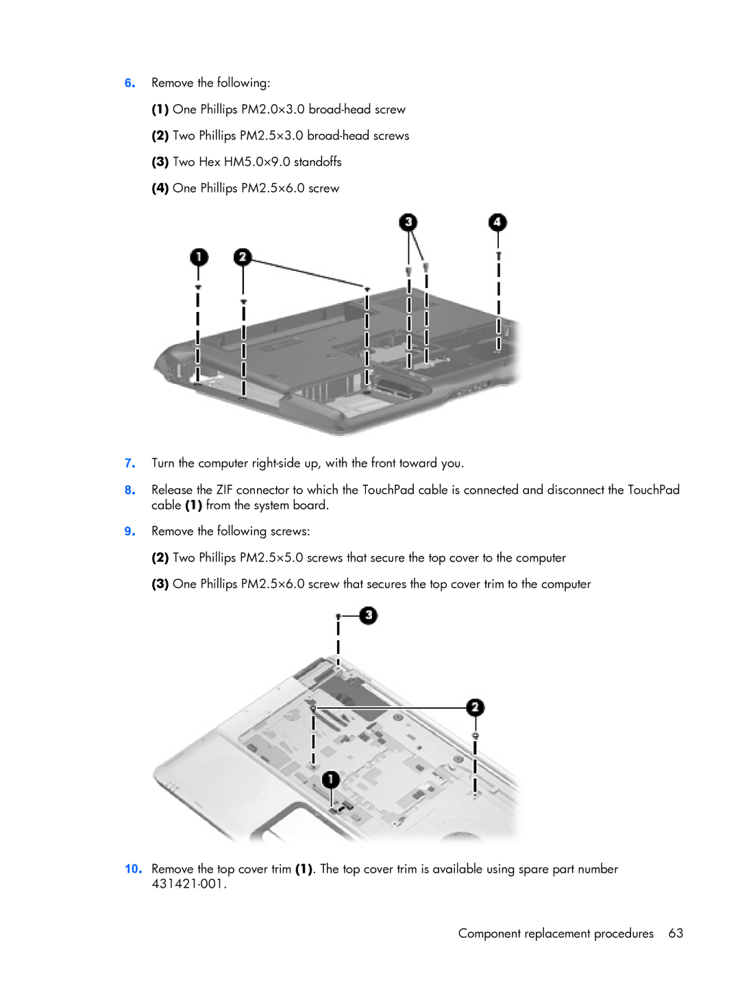
6. Remove the following:
(1)One Phillips PM2.0×3.0
(2)Two Phillips PM2.5×3.0
(3)Two Hex HM5.0×9.0 standoffs
(4)One Phillips PM2.5×6.0 screw
7. Turn the computer
8. Release the ZIF connector to which the TouchPad cable is connected and disconnect the TouchPad cable (1) from the system board.
9. Remove the following screws:
(2)Two Phillips PM2.5×5.0 screws that secure the top cover to the computer
(3)One Phillips PM2.5×6.0 screw that secures the top cover trim to the computer
10. Remove the top cover trim (1). The top cover trim is available using spare part number
Component replacement procedures 63
