Modular Cooling System specifications
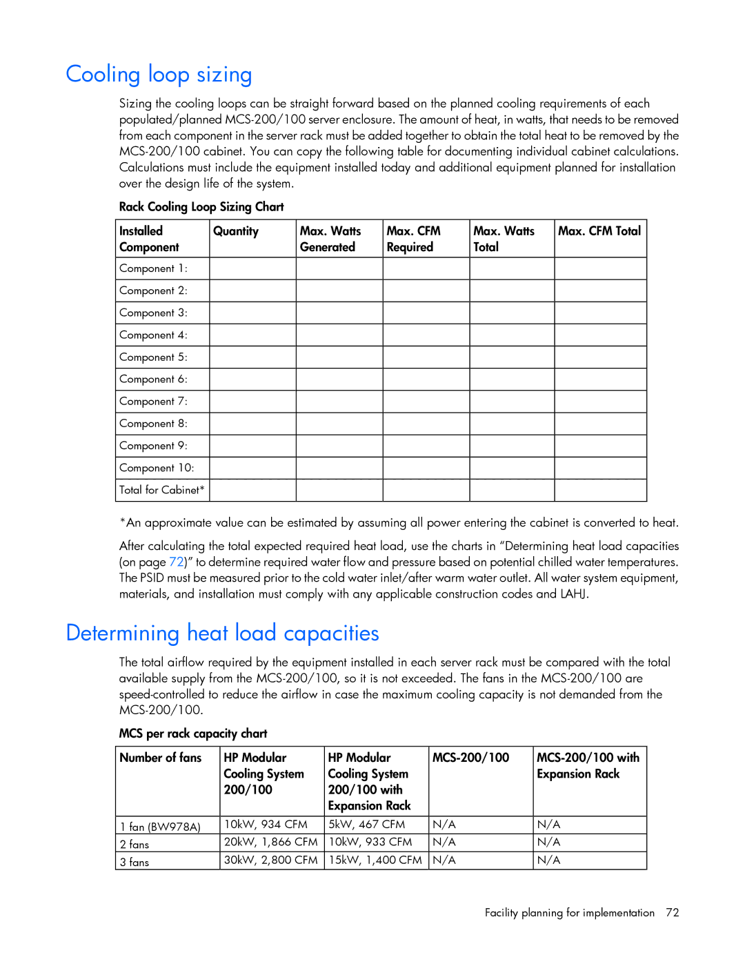
The HP Modular Cooling System (MCS) is a state-of-the-art solution designed to efficiently manage the heat generated by high-density IT environments. As data centers face the ever-increasing demand for processing power, traditional cooling methods often fall short, leading to inefficiencies and raised energy costs. The HP MCS addresses this issue with a scalable, flexible design that optimizes cooling performance while minimizing energy consumption.One of the main features of the HP Modular Cooling System is its modular architecture, which allows for easy expansion and customization based on the specific needs of a data center. This scalability means that as a facility grows or changes, the cooling system can be modified without the need for extensive renovations or replacements. The MCS can be installed in various configurations, further enhancing its versatility.
The technology behind the HP MCS includes advanced cooling methods such as direct evaporative cooling and chilled water cooling. Direct evaporative cooling utilizes the principles of evaporative heat exchange to cool air without excessive energy consumption, making it an eco-friendly choice. In contrast, chilled water cooling uses a network of pipes filled with chilled water to remove heat from the server environment efficiently. This combination allows the MCS to adapt to various heat loads and ambient conditions.
Another notable characteristic of the HP Modular Cooling System is its intelligent controls and sensors. These components continually monitor temperature and humidity levels within the data center, automatically adjusting cooling output to maintain optimal conditions. This proactive approach helps to prevent overheating, reduces energy usage, and ensures the longevity of IT equipment.
Energy efficiency is further enhanced through the MCS's integration with HP's monitoring and management software. This software analyzes cooling performance trends, providing actionable insights for facility managers, enabling them to make informed decisions regarding cooling strategies. Additionally, the system is designed with environmentally sustainable practices in mind, aligning with global initiatives to reduce carbon footprints and promote green technology.
The HP Modular Cooling System stands out for its combination of innovative technologies, flexibility, and a commitment to energy efficiency. As data centers continue to evolve, the MCS remains a crucial asset in the pursuit of optimized performance and sustainability, providing a reliable solution to meet the demanding cooling needs of modern IT infrastructure.
