Appendix B LEDs
Panel LEDs
Figure 35 |
|
|
| |
4 |
|
|
| |
3 | 5 6 | 5 | 6 | |
2 | ||||
|
|
| ||
1 |
|
|
|
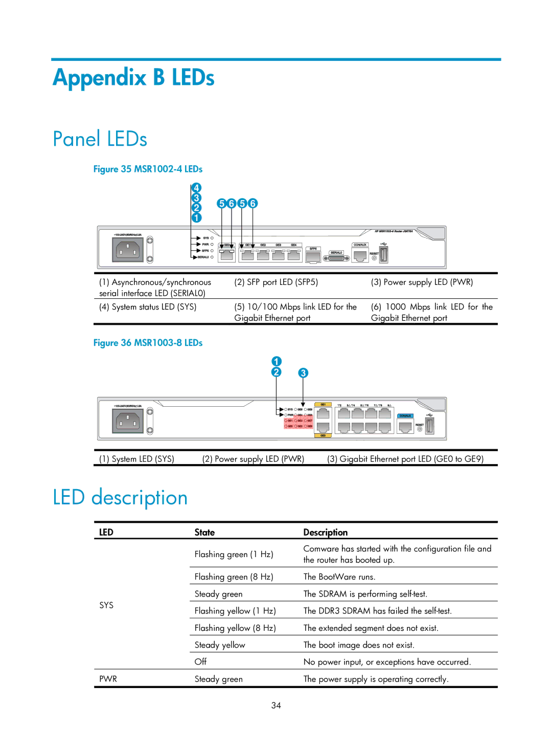
(1) Asynchronous/synchronous | (2) SFP port LED (SFP5) | (3) Power supply LED (PWR) |
serial interface LED (SERIAL0) |
|
|
(4) System status LED (SYS) | (5) 10/100 Mbps link LED for the |
| Gigabit Ethernet port |
(6)1000 Mbps link LED for the Gigabit Ethernet port
Figure 36 MSR1003-8 LEDs
(1) System LED (SYS) | (2) Power supply LED (PWR) | (3) Gigabit Ethernet port LED (GE0 to GE9) |
LED description
LED
SYS
PWR
State | Description | |
Flashing green (1 Hz) | Comware has started with the configuration file and | |
the router has booted up. | ||
| ||
|
| |
Flashing green (8 Hz) | The BootWare runs. | |
|
| |
Steady green | The SDRAM is performing | |
|
| |
Flashing yellow (1 Hz) | The DDR3 SDRAM has failed the | |
|
| |
Flashing yellow (8 Hz) | The extended segment does not exist. | |
|
| |
Steady yellow | The boot image does not exist. | |
|
| |
Off | No power input, or exceptions have occurred. | |
Steady green | The power supply is operating correctly. |
34
