Maintenance and Service Guide
Page
Contents
Illustrated Parts Catalog
Removal and Replacement Procedures
Contents
Product Description
Features
Product Description
Resetting the Computer
Power Management
Front Components
External Components
Component Function
Front Components
Right-Side Components
Right-Side Components
Left-Side Components
Left-Side Components
Rear Panel Components
Rear Panel Components
Standard Keyboard Components
Standard Keyboard Components
Fn key
Top Components, Part
Top Components, Part
Computer top components are below and described in Table
Component Function
Bottom Components
Bottom Components
Design Overview
Troubleshooting
Computer Setup
Troubleshooting
Computer Setup Defaults
File Menu
Select To Do This
Security Menu
Diagnostics Menu
System Configuration Menu
Setup even when a Microsoft Windows
System Configuration Menu
Troubleshooting Flowcharts
Troubleshooting Flowcharts Overview
Flowchart 2.1-Initial Troubleshooting
Flowchart No Power Part
Flowchart 2.2-No Power, Part
Flowchart 2.3-No Power, Part
Flowchart 2.4-No Power, Part
External
Flowchart 2.5-No Power, Part
Flowchart 2.6-No Video, Part
Flowchart 2.7-No Video, Part
Flowchart No Video Part
Flowchart 2.8-Nonfunctioning Docking Device if applicable
Flowchart 2.9-No Operating System OS Loading
Go to Flowchart 2.13-No OS Loading Diskette Drive
Flowchart 2.10-No OS Loading, Hard Drive, Part
Loading
Flowchart 2.11-No OS Loading, Hard Drive, Part
Flowchart No OS Loading Hard Drive, Part
Flowchart 2.12-No OS Loading, Hard Drive, Part
Flowchart 2.13-No OS Loading, Diskette Drive
Flowchart 2.14-No OS Loading, Optical Drive
Flowchart 2.15-No Audio, Part
Flowchart 2.16-No Audio, Part
Flowchart 2.17-Nonfunctioning Device
Cmos
Flowchart 2.18-Nonfunctioning Keyboard
Flowchart 2.19-Nonfunctioning Pointing Device
Pointing device Not operating Properly Connect computer
Flowchart 2.20-No Network/Modem Connection
Illustrated Parts Catalog
Serial Number Location
Computer Major Components
Item Description Number
Spare Parts Computer Major Components
Keyboards
Computer Major Components
Fan
Spare Part
Description Number
Mini Card modules
Computer Major Components
Thermal Grease Kit not illustrated
Description Number Plastics Kit
Memory modules
Computer Major Components
Base enclosures
Speaker
Batteries
Computer Major Components
Optical drives include bezel and optical drive bracket
Plastics Kit Spare Part Number Information
Plastics Kit
Item Description Number Plastics Kit 430884-001 Includes
Cable Kit Spare Part Number Information
Cable Kit
Item Description Number Cable Kit 430883-001 Includes
Mass Storage Devices Spare Part Number Information
Mass Storage Devices
Optical drives include bezel
Miscellaneous Not Illustrated
Miscellaneous Not Illustrated Spare Part Information
Description Number Power cords
Appendix A, Screw Listing, for more information on
Sequential Part Number Listing
Sequential Part Number Listing
Spare Part Number Description
Venezuela
Sequential Part Number Listing
Sequential Part Number Listing
432160-001 Plastics Kit
Sequential Part Number Listing
Sequential Part Number Listing
Removal and Replacement Preliminaries
Tools Required
Service Considerations
Plastic Parts
Preventing Damage to Removable Drives
Preventing Electrostatic Damage
Packaging and Transporting Precautions
Workstation Precautions
Use the following grounding precautions at workstations
Grounding Equipment and Methods
Relative Humidity Event 10% 40% 55%
Typical Electrostatic Voltage Levels
Static-Shielding Materials
Material Use Voltage Protection Level
Removal and Replacement Procedures
Serial Number
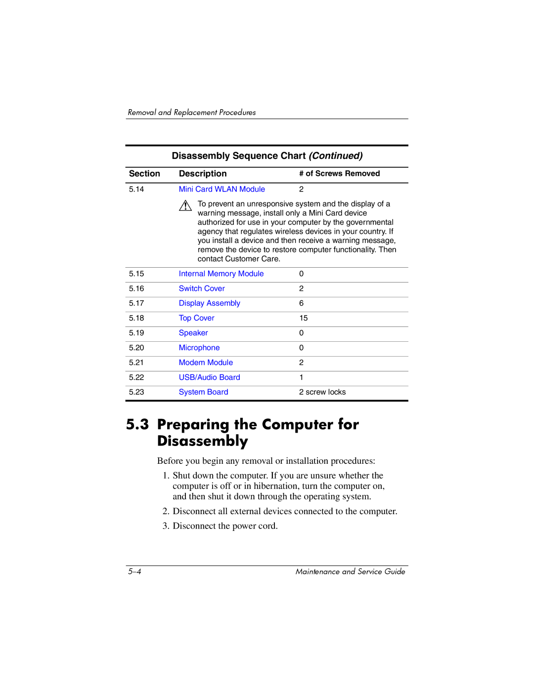
Disassembly Sequence Chart
Disassembly Sequence Chart
# of Screws Removed
Preparing the Computer for Disassembly
Mini Card Wlan Module
Battery Spare Part Number Information
Hard Drive
Hard Drive Spare Part Number Information
Removing the Hard Drive Cover
Removing the Hard Drive
Removing the Hard Drive Frame
Computer Feet
Bluetooth Module
Bluetooth Module Spare Part Number Information
External Memory Module
Memory Module Spare Part Number Information
Reverse the above procedure to install a memory module
Optical Drive
Optical Drive Spare Part Number Information
Removing the Optical Drive
Keyboard
Keyboard Spare Part Number Information
Removing the Keyboard Screws
Releasing the Keyboard
Disconnecting the Keyboard Cable
10 Fan
Fan Spare Part Number Information
Heat Sink
Heat Sink Spare Part Number Information
Removing the Heat Sink
Reverse the above procedure to install the heat sink
Processor
Processor Spare Part Number Information
Reverse the above procedure to install the processor
RTC Battery
Mini Card Wlan Module
Mini Card Wlan Module Spare Part Number Information
Removing a Mini Card Wlan Module
Internal Memory Module
Reverse the above procedure to install a memory module
Switch Cover
Switch Cover Spare Part Number Information
Reverse the above procedure to install the switch cover
Display Assembly
Display Assembly Spare Part Number Information
Removing the Display Assembly Screws
Removing the Display Assembly
Top Cover
Top Cover Spare Part Number Information
Removing the Top Cover Screws, Part
Removing the Top Cover Screws, Part
Releasing the Top Cover
Speaker
Speaker Spare Part Number Information
Reverse the above procedure to install the speaker
Microphone
Reverse the above procedure to install the microphone
Modem Module
Modem Module Spare Part Number Information
Reverse the above procedure to install the modem module
22 USB/Audio Board
USB/Audio Board Spare Part Number Information
Reverse the above procedure to install the USB/audio board
System Board
System Board Spare Part Number Information
Speaker Section
Reverse the above procedures to install the system board
Input Power
Dimensions Metric
Weight
Temperature
Shock
Relative humidity noncondensing
Maximum altitude unpressurized
Random Vibration
Inch, SXGA+WVA, TFT Display
Inch, XGA, TFT Display
Hard Drives
Primary 6-cell, Li-Ion Battery
Energy
Center hole diameter
DVD/CD-RW Combo Drive
Applicable disc Read Write
Disc diameter
Track pitch
Access time
Disc thickness
Audio output level
DVD±RW and CD-RW Combo Drive
DVD
CD-ROM Drive
Applicable disc
System DMA
Hardware DMA System Function
System Interrupts
Hardware IRQ System Function
IRQ12
System I/O Addresses
Address hex
16F Unused
VGA
System Memory Map
Size Memory Address System Function
Screw Listing
Table A-1 Phillips PM2.0×5.0 Screw
Color Qty Length Thread Width Black Where used
Head
Color Qty Length Thread Width Silver 13.0 mm Where used
Color Qty Length Thread Width Silver Where used
Table A-3 Phillips PM3.0×4.0 Screw
Table A-4 Torx8 T8M2.5×9.0 Screw
Table A-4 Torx8 T8M2.5×9.0 Screw
Table A-4 Torx8 T8M2.5×9.0 Screw
Table A-5 Phillips PM2.0×3.0 Screw
Phillips PM2.0×3.0 Screw Location
Table A-6 Torx8 T8M2.5×2.0 Screw
Table A-7 Phillips PM2.0×7.0 Screw
Table A-7 Phillips PM2.0×7.0 Screw
Table A-8 Phillips PM2.5×4.0 Screw
Table A-9 Hex Socket HM5.0×9.0 Screw Lock
Head Color Qty. Length Thread Width
Backup and Recovery
Backup
Backing Up the System
Backing Up Specific Files or Folders
Backing Up the Entire Hard Drive
Backing Up Modifications Made to the System
Recovery
Scheduling Backups
Creating Recovery Discs Highly Recommended
Performing a Recovery
Performing a Recovery from the Recovery Discs
Performing a Recovery from the Hard Drive
Initiating a Recovery in Windows
Display Component Recycling
Display Component Recycling
Removing the Display Bezel Screw Covers and Screws
Removing the Display Bezel
Removing the Display Inverter
Removing the Display Panel Assembly
Removing the Display Panel Frame Screws
Removing the Display Frame
Removing the Backlight Cover
Releasing the Backlight Cables
Removing the Backlight Frame
Slide the backlight out of the backlight frame
Releasing the LCD Panel
Remove the LCD panel
Pin Signal
Table D-1 Audio-Out Headphone
Table D-2 Audio-In Microphone
Table D-3 Universal Serial Bus
Table D-4 Video-Out
TV-CD
Table D-5 External Monitor
Table D-6 RJ-11 Modem
Table D-7 RJ-45 Network
Power Cord Set Requirements
Conductor Power Cord Set
General Requirements
Country-Specific Requirements
Conductor Power Cord Set Requirements
Country/Region Accredited Agency Applicable Note Number
Kema
Index
Index
Index-3
Index-4
Troubleshooting 2-18,2-27num lock key
Index-6
Index-7