Maintenance and Service Guide
Page
Contents
Removal and Replacement Preliminaries
Removal and Replacement Procedures
Screw Listing Index
Product Description
Models
Key Description Options
Key
HP Pavilion zt3000 Models
Model Naming Convention
DR254A UUF
DR259A UUF
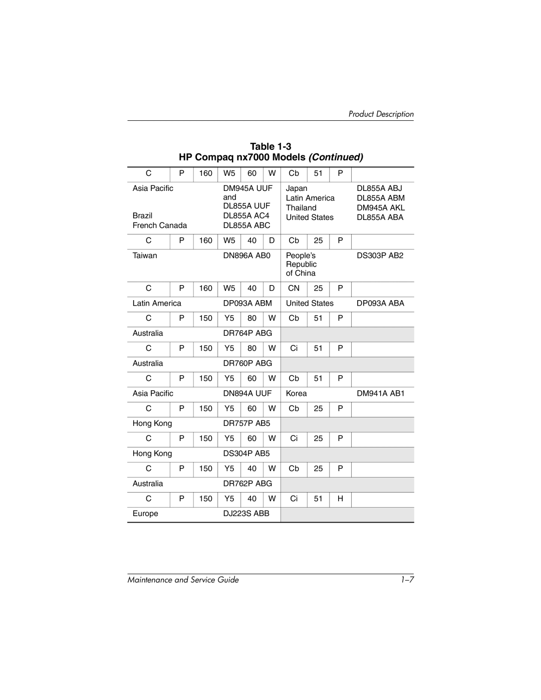
HP Compaq nx7000 Models
DM945A UUF
DG705A UUG
DJ169S UUZ
DL844A UUF
DG704A UUG
DR850P UUF
Compaq Presario X1000 Models
DN591A ABG
Compaq Presario X1000 Models
DM774A ABA
DN593A UUF
DN583A UUF
DM415A ABF
DP771E ABU
DN599A AKL
DN594A UUF
Features
Product Description
Clearing a Password
Power Management
External Components
Front and Left-Side Components
Component Function
Rear Panel and Right-Side Components
Rear Panel and Right-Side Components
Keyboard Components
Keyboard Components
Num lk key
Top Components
Top Components
Bottom Components
Bottom Components
Design Overview
Troubleshooting
Computer Setup and Diagnostics Utilities
Using Computer Setup
File Menu
Select To Do This
Selecting from the Security Menu
Security Menu
Selecting from the Advanced Menu
Advanced Menu
Advanced Menu
Troubleshooting Flowcharts
Troubleshooting Flowcharts Overview
Flowchart Description
Flowchart 2.1-Initial Troubleshooting
Go to Flowchart No Power
Flowchart 2.2-No Power, Part
Power? Go to Flowchart No Power Part Power up On AC Reset
Flowchart 2.3-No Power, Part
Flowchart 2.4-No Power, Part
Flowchart 2.5-No Power, Part
Flowchart 2.6-No Video, Part
Flowchart 2.7-No Video, Part
From Flowchart No Video, Part Remove
Flowchart 2.8-Nonfunctioning Port Replicator if applicable
Reseat power Cord in port
Flowchart 2.9-No Operating System OS Loading
Flowchart 2.10-No OS Loading, Hard Drive, Part
Flowchart 2.11-No OS Loading, Hard Drive, Part
Flowchart 2.12-No OS Loading, Hard Drive, Part
Flowchart 2.13-No OS Loading, CD- or DVD-ROM Drive
Flowchart 2.14-No Audio, Part
Go to Flowchart No Audio, Part Undock
Flowchart 2.15-No Audio, Part
Flowchart 2.16-Nonfunctioning Device
Cmos
Flowchart 2.17-Nonfunctioning Keyboard
Flowchart 2.18-Nonfunctioning Pointing Device
Flowchart 2.19-No Network/Modem Connection
Illustrated Parts Catalog
Serial Number Location
Illustrated Parts Catalog
Spare Parts Notebook Major Components
Item Description Number
Spare Part
Display assemblies
Illustrated Parts Catalog
Spare Part
Description Number
Illustrated Parts Catalog
PC Card assembly not illustrated
Left and right wireless antennae with cables
Left and right speakers not illustrated
Heat sink with fan
Illustrated Parts Catalog
Battery pack, 8-cell, 4.4-wH
Miscellaneous Doors/Covers Kit , includes
Mini PCI communications boards
Memory expansion boards
Miscellaneous Plastics Kit Components
Item Description
Miscellaneous Cable Kit Components
Miscellaneous Cable Kit Components Spare Part Number
Miscellaneous Doors/Covers Kit Components
Miscellaneous Doors/Covers Kit Components Spare Part Number
Mass Storage Devices
Mass Storage Devices Spare Part Number Information
USB diskette drive not illustrated
Miscellaneous
Miscellaneous not illustrated Spare Part Information
Description Spare Part Number
Spare Part Information
Miscellaneous not illustrated
Removal and Replacement Preliminaries
Tools Required
Service Considerations
Plastic Parts
Preventing Damage to Removable Drives
Packaging and Transporting Precautions
Preventing Electrostatic Damage
Workstation Precautions
Grounding Equipment and Methods
Typical Electrostatic Voltage Levels
Static-Shielding Materials
Event 10% 40% 55%
Material Use Voltage Protection Level
Removal and Replacement Procedures
Serial Number
Disassembly Sequence Chart
Disassembly Sequence Chart
# of Screws
Section Description Removed
Preparing the Notebook for Disassembly
Lift the front edge of the battery pack up and swing it back
Remove the hard drive
Removing the Hard Drive from the Hard Drive Cover
Replacing the Notebook Feet
Memory Expansion Board
Removing the Memory Expansion Board
Mini PCI Communications Board
Removing the Mini PCI Communications Board
RTC Battery
Optical Drive
Keyboard
Releasing the Keyboard
Disconnecting the Keyboard Cable
Switch Cover
Speaker Cover
Reverse the above procedure to install the speaker cover
12 Fan
Heat Sink
Reverse the above procedure to install the heat sink
Processor
Reverse the above procedure to install the processor
Display Assembly
Disconnecting the Display Cable
Removing the Display Screws
Reverse the above procedure to install the display assembly
Top Cover
Removing the Top Cover Screws
Removal and Replacement Procedures
Disconnecting the Bluetooth Wireless Module Speaker Cables
Removing the Top Cover Screws
Reverse the above procedure to install the top cover
Bluetooth Board
Reverse the above procedure to install the Bluetooth board
SD Card Slot Board and Cable
Removing the SD Card Slot Board and Cable
VGA Board and Shield
Removing the VGA Board and Shield
Modem and Cable
Reverse the above procedure to install the modem and cable
System Board
Removing the System Board Screws
Reverse the above procedure to install the system board
Dimensions
Stand-alone power requirements
Temperature
Relative humidity noncondensing
Shock
Inch, Wide UXGA, TFT Display
Inch, Wide SXGA+, TFT Display
Inch, Wide XGA+, TFT Display
Hard Drives
80-GB 60-GB 40-GB 5400 4200 Rpm
Cell, Primary Li-Ion Battery Pack
External AC Adapter
24X DVD/CD-RW Drive
24X CD-RW Drive
8X DVD-ROM Drive
Track pitch Access time
24X CD-ROM Drive
System DMA
Hardware System
System Interrupts
IRQ
System I/O Addresses
Address System Function
16F Unused
VGA
Pin Signal
RJ-45 Network Interface
Table A-2 RJ-11 Modem
Table A-3 Universal Serial Bus
Table A-4 Video
Table A-5 External Monitor
Pin Signal Audio out
Pin Signal Audio
Microphone
Table A-8 Parallel
Conductor Power Cord Set
General Requirements
Conductor Power Cord Set Requirements
Country-Specific Requirements
Applicable Note
Country Accredited Agency Number
BSI
Screw Listing
Black Where used
Table C-1 Phillips PM2.5×9.5 Screw
Head
Color Qty Length Thread Width
Head Color Qty. Length Thread Width
Table C-2 Phillips PM2.5×7.0 Screw
Table C-2 Phillips PM2.5×7.0 Screw
Silver Where used
Table C-3 Phillips PM2.5×3.5 Screw
Table C-4 Phillips PM2.5×5.0 Screw
Table C-4 Phillips PM2.5×5.0 Screw
Table C-4 Phillips PM2.5×5.0 Screw
Table C-4 Phillips PM2.5×5.0 Screw
Phillips PM2.5×5.0 Screw Location
Table C-4 Phillips PM2.5×5.0 Screw
Table C-4 Phillips PM2.5×5.0 Screw
Black 15.0 mm Where used
Table C-5 Phillips PM2.5×15.0 Screw
Table C-5 Phillips PM2.5×15.0 Screw
Table C-5 Phillips PM2.5×15.0 Screw
Table C-6 Phillips PM2.5×3.0 Screw
Table C-7 Phillips PM2.0×3.0 Screw
Table C-8 Phillips PM2.0×9.0 Spring-Loaded Screw
Table C-9 Phillips PM1.5×3.0 Screw
Index
Index
Index-3
Index-4
Index-5
Index-6