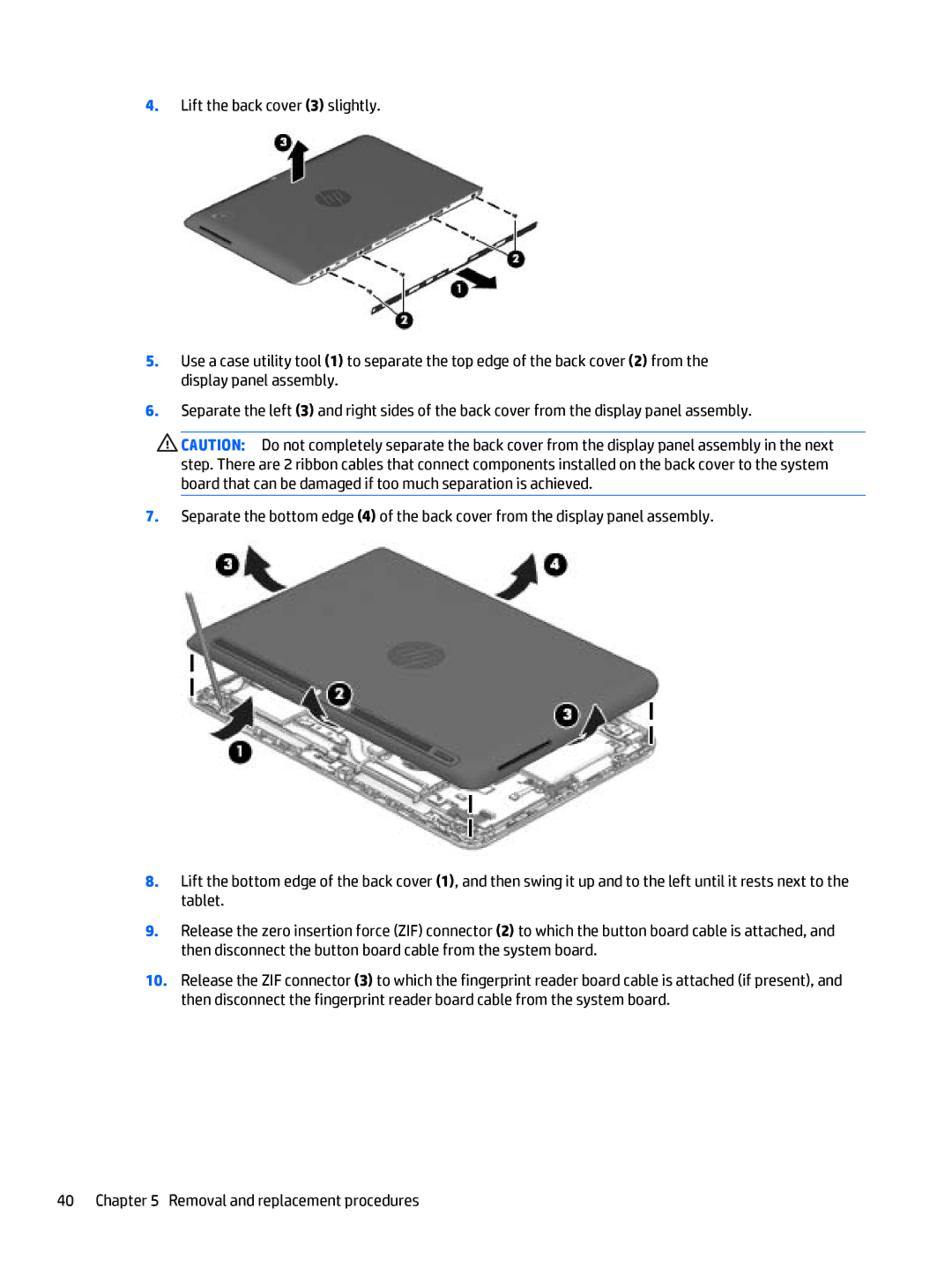
4.Lift the back cover (3) slightly.
5.Use a case utility tool (1) to separate the top edge of the back cover (2) from the display panel assembly.
6.Separate the left (3) and right sides of the back cover from the display panel assembly.
![]() CAUTION: Do not completely separate the back cover from the display panel assembly in the next step. There are 2 ribbon cables that connect components installed on the back cover to the system board that can be damaged if too much separation is achieved.
CAUTION: Do not completely separate the back cover from the display panel assembly in the next step. There are 2 ribbon cables that connect components installed on the back cover to the system board that can be damaged if too much separation is achieved.
7.Separate the bottom edge (4) of the back cover from the display panel assembly.
8.Lift the bottom edge of the back cover (1), and then swing it up and to the left until it rests next to the tablet.
9.Release the zero insertion force (ZIF) connector (2) to which the button board cable is attached, and then disconnect the button board cable from the system board.
10.Release the ZIF connector (3) to which the fingerprint reader board cable is attached (if present), and then disconnect the fingerprint reader board cable from the system board.
40 Chapter 5 Removal and replacement procedures
